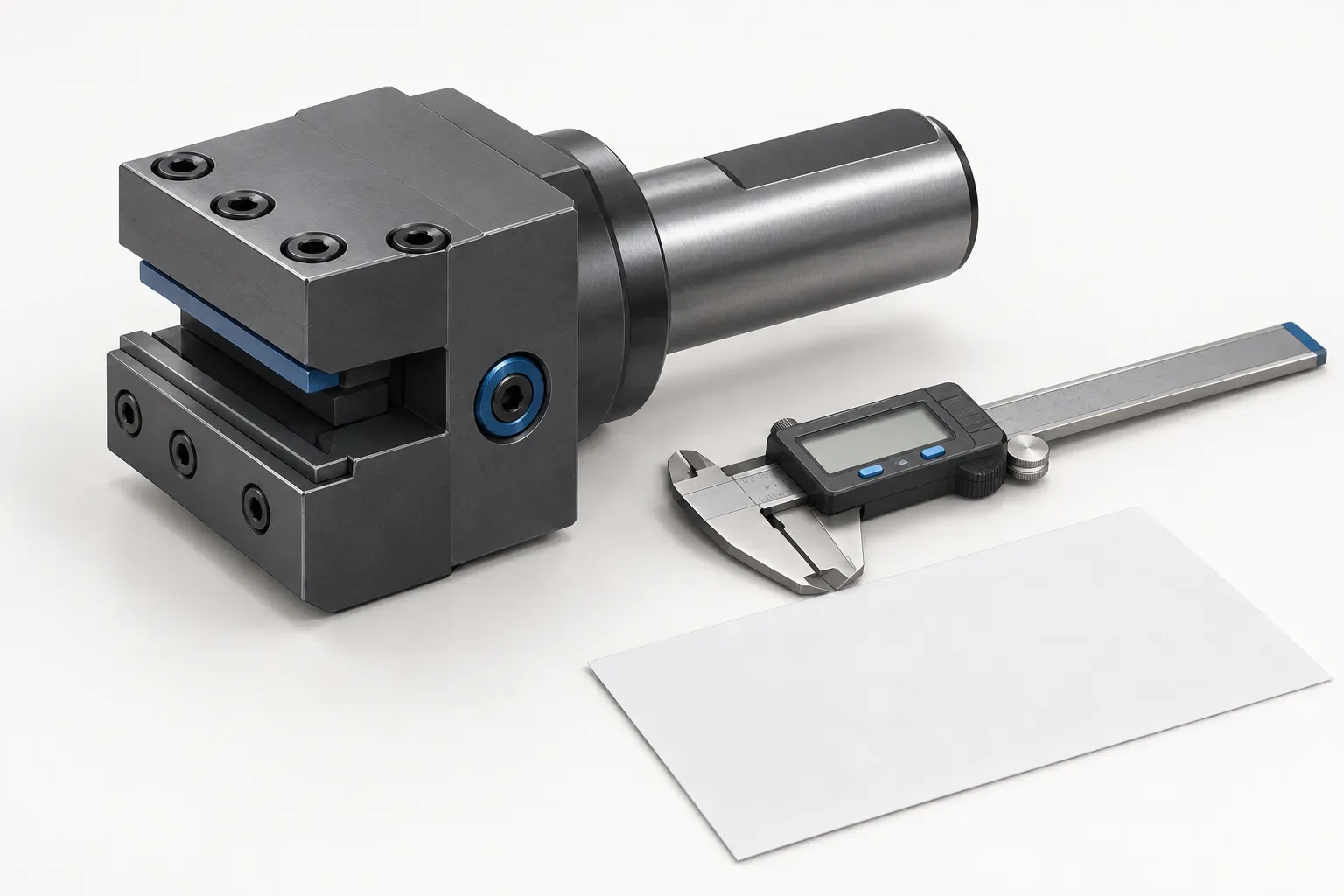
VDI tool holders should be selected by the turret interface, tool orientation, holder form and complete drawing dimensions—not by a familiar-looking model code alone. A replacement must position the cutting tool correctly and fit the available working space. Start with the machine and turret documentation, then compare the exact holder configuration against its dimensional drawing.
This guide explains how to organize that comparison using two listed configurations: a right-hand, short radial holder and a right-hand axial holder. Their measurements are examples for those specific products, not dimensions shared by all VDI tooling.
Identify the holder arrangement before comparing sizes
Record whether the job needs a radial or axial tool arrangement, the required direction, and the holder form. These descriptions help separate configurations that might otherwise look similar in a catalogue. A matching interface diameter alone does not establish that the holder places the tool in the required position.
The local range identifies B1-16x12x24 as a right-hand, short radial tool holder. C1-16x12x44 is identified as a right-hand axial tool holder. Treat those descriptions as part of each product identity. Do not assume that the letters used for one series describe every manufacturer's naming system.
If replacing an existing holder, photograph its installed orientation and record the tool position relative to the workpiece. Include any readable identification on the old holder. That information makes the dimensional comparison more useful than an isolated photograph of an uninstalled component.
Read the dimensions alongside the drawing
The B1-16x12x24 radial holder has the following listed dimensions. The original drawing establishes where each label is measured; the letters should stay attached to the values when preparing an enquiry.
| Drawing field | Listed value |
|---|---|
| Diameter d1 | 16 mm |
| Width b1 | 42 mm |
| Width b2 | 23 mm |
| Height h1 | 12 mm |
| Length l1 | 13 mm |
| Length l2 | 24 mm |
These are selected dimensions, not the entire installation envelope. The product also lists other width and height fields. Compare the complete drawing rather than treating this shortened table as a manufacturing specification.
Do not decode every number in a compound model into an assumed dimension. The model identifies a configuration; the labelled table and drawing explain its measurements. In particular, a field called height should not automatically become a centre-height claim unless the drawing establishes that meaning.
Compare radial and axial configurations explicitly
For the C1-16x12x44 axial holder, the listed diameter d1 is also 16 mm, but width b1 is 43 mm and length l1 is 44 mm. Those values differ from the radial example even though both list a 16 mm d1.
This comparison shows why a shared diameter cannot substitute for an installation check. It does not prove that these two holders are interchangeable, nor does it establish compatibility with any named machine. Match the complete arrangement to the turret documentation and the intended tool position.
When comparing another size in the same family, verify its own row in the specification table. Do not carry widths, heights or lengths across sizes simply because their product photographs look alike. Series photographs can represent multiple configurations.
Check the working envelope with the tool installed
Review the assembly with the intended cutting tool, not just the empty holder. Note the tool section or shank requirements, cutting-edge position and available clearance around adjacent tooling, the chuck and the workpiece. The amount of clearance required depends on the actual machine, setup and programmed motion.
A drawing review should also identify any installation details that have not been established by the listing. Clamping instructions, tightening values, coolant connections and machine-specific restrictions must come from the applicable documentation or tool manufacturer. Do not derive them from appearance or from another holder's instructions.
If the available information does not resolve a fit question, describe that question before ordering. A marked-up drawing showing the uncertain surface or dimension is more precise than asking whether a holder is generally suitable for a machine family.
Prepare a clear VDI tooling enquiry
Use the tool holders and adapters catalogue to identify candidates, then prepare a single configuration record:
- Exact holder model and required quantity.
- Machine and turret identification, with the relevant interface drawing if available.
- Radial or axial arrangement, direction and required holder form.
- Cutting-tool dimensions and the intended tool position.
- Relevant drawing labels, units and any restricted installation space.
- Questions about clamping, accessories or coolant provisions that remain unresolved.
Keeping those details together reduces the chance of discussing one holder while quoting the dimensions of another. A quotation should identify the selected configuration and included items explicitly. Neither an illustrative image nor a short model description establishes an accessory package.
Frequently asked questions
Does a matching VDI diameter guarantee that a holder fits?
No. Compare the exact interface, holder arrangement, direction and full drawing dimensions with the turret documentation. Matching one diameter does not establish tool position or clearance.
Can I use a radial holder model code to choose an axial holder?
Use the actual product identity and dimensional drawing for the required arrangement. The two examples here are separately identified radial and axial configurations; their shared d1 value does not make them interchangeable.
What should I send when the old holder model is unreadable?
Provide machine and turret details, photographs showing installation and tool orientation, a dimensional sketch with units, and the cutting-tool requirements. Identify unresolved measurements rather than assuming a model from appearance.