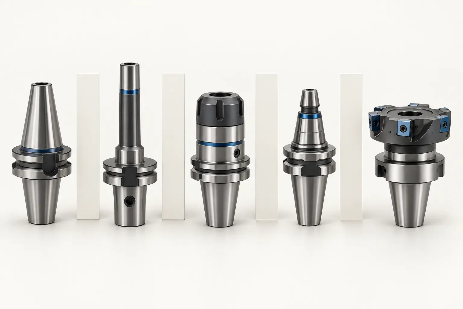
CNC tool holders should be chosen by the interfaces and tool arrangement required for an operation. The phrase covers different product forms, so the first purchasing question is not simply which size to order. It is which component must connect the machine or turret to the intended cutting tool.
This guide helps organize that first selection. It distinguishes holder identity, machine-side requirements and tool-side requirements, then shows how to prepare a configuration record that can be used for a quotation. It does not claim that the product families discussed are interchangeable.
Identify the component being requested
A turret-mounted boring holder, a radial turning-tool holder and a face mill arbor are different items. Their drawings describe different features because they perform different roles in an assembly. A broad request for a CNC holder can therefore lead to unrelated candidates unless the operation and tool are identified.
Start with the cutting task and the machine arrangement. Describe the actual tool that must be supported and show the relevant interface from the machine documentation. If the request concerns a replacement, include the complete old designation where readable and explain its installed position.
Avoid assuming that a product code shared in a photograph identifies the complete assembly. Separate the holder, cutting tool and any adapter or accessory so that each required item can be discussed accurately.
Use two interfaces to organize the comparison
The machine side concerns how the component locates and fastens to its mounting arrangement. The tool side concerns how the intended cutting tool or another assembly component is supported. Both interfaces require their own documented information.
| Selection question | Information to identify |
|---|---|
| Which component is required? | Holder form and intended operation |
| What connects to the machine? | Actual interface drawing and locating arrangement |
| What connects to the tool? | Tool dimensions and documented clamping or mating requirements |
| Where must it work? | Assembled tool position and available envelope |
| What is being purchased? | Exact configuration and separately specified included items |
This structure prevents an enquiry from treating one nominal diameter as proof of fit. It also keeps the tool requirement visible when a different machine-side configuration is proposed.
Read dimensions in their product context
The BMT40-B25-H60 boring holder records a 25 mm tool bore and a 60 mm bore centre height. Those fields describe different features of that specific holder.
The B1-16x12x24 VDI radial holder instead records a diameter d1 of 16 mm and several separately labelled widths, heights and lengths. It is identified as right-hand and short. Its height labels should not be given the BMT example's bore-centre meaning without drawing evidence.
These examples show why an all-purpose comparison sheet needs feature names and units, not only model strings and numbers. A shared label such as height or length may refer to a different physical feature in another product family.
Check the complete assembly and working space
Once a candidate is identified, include the actual cutting tool and any separately specified connecting component in the review. Record the intended clamping region, required reach and cutting position using the relevant drawings.
Consider the workpiece, chuck and adjacent tooling in the planned arrangement. The holder dimensions do not provide a universal clearance allowance or establish that a programmed motion is free from collision. The actual machine setup must resolve those questions.
Do not infer accuracy, allowable load, balancing condition or cutting performance from a product's outside dimensions. Where those properties are important, obtain evidence and instructions applicable to the exact component and assembled use.
Keep unknowns specific and visible
An incomplete record should lead to a precise question. Identify the uncertain interface, mounting feature, tool position or installation requirement and show it on a drawing. That is more useful than asking whether a holder is generally suitable for CNC work.
Do not fill gaps with dimensions copied from a similar photograph or another configuration. The difference may be exactly what determines whether the assembly is suitable. Keep proposed alternatives in separate rows until their own documentation has been reviewed.
Prepare a configuration-specific enquiry
Provide machine and turret details where relevant, the intended operation, cutting-tool information, required quantity and supporting drawings. Identify the complete holder configuration and list accessories separately. Ask the quotation to specify what is included and obtain the applicable installation instructions before assembly.
The tool holders and adapters catalogue can help locate the relevant family. Use that family-level navigation to begin the search, then make the final comparison using the exact configuration record. This keeps a broad CNC tooling request focused on an identifiable component and an actual purchasing task.
Frequently asked questions
Does CNC tool holder identify a single product type?
No. The required holder form and operation must be identified before selecting a specific component.
Why compare the machine side and tool side separately?
They concern different mating requirements. A match at one side does not establish that the complete assembly is suitable.
Can a similar photograph supply missing dimensions?
No. Use the specific drawing and configuration record, and identify unanswered questions explicitly.