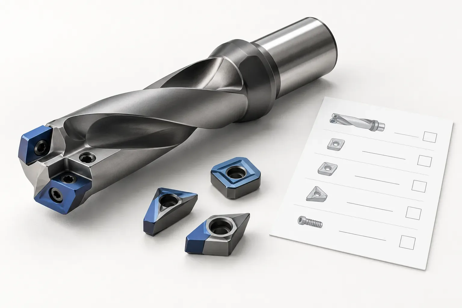
An enquiry about U drills should identify the actual drilling system, body and cutting components rather than rely on the search term as a complete specification. Before requesting a body, establish the hole requirement, machine-side interface and the components that must be supplied with it. A familiar family name does not prove a particular configuration or cross-system compatibility.
This is a general purchasing guide for evaluating a drilling-body requirement. It does not assign unverified dimensions, cutting conditions or stock status to a product on this site. Any proposed item still needs its own verified record and applicable installation information.
Define whether the purchase concerns a body or a complete assembly
State the required item at the start of the enquiry. If the requirement is for a body, identify which cutting components and accessories are already available. If the requirement is a complete assembly, ask for its supplied items to be listed rather than assuming that everything visible in an illustration is included.
Avoid calling an unfamiliar product interchangeable merely because it is described with the same broad search term. Body identity, cutting-component requirements and installation geometry are separate checks. The quotation needs enough information to reproduce the actual proposed configuration.
If replacing an existing body, retain its readable identification and photographs showing the shank, cutting-component positions and relevant interfaces. Do not infer hidden geometry or a missing product suffix from a distant photograph.
Describe the hole and installation constraints
Provide the required diameter and depth from the drawing, along with whether the feature is blind or through. Identify the surface condition at entry, any existing hole and any obstruction affecting approach. Keep the finished feature requirement distinct from the process used to produce it.
State the actual workpiece material and its known condition. An application label such as general steelwork is not a substitute for a material description when the cutting-element selection depends on it. If the material or condition remains unconfirmed, record that question explicitly.
Also provide the machine and holder information needed to evaluate the proposed shank and installation. Nominal cutting size and holding dimensions answer different questions. Check the complete installed position rather than assuming that catalogue length is available cutting reach.
Match the cutting components to the identified body
Where the selected system uses replaceable cutting components, obtain the body-specific component requirement. Keep the complete designation and any required suffix together. A partial family code cannot establish the grade, geometry or other details needed for the intended material and operation.
Do not combine a body from one record with a cutting component from another because they look similar. Identify each required position according to the actual documentation. If the system distinguishes component positions, the enquiry should preserve those distinctions rather than ordering an unspecified group of apparently matching inserts.
This guide does not assume how many cutting components a particular body contains. That count must come from the verified item and its supplied-item list. The same applies to screws, keys and other installation accessories.
Review the interface and coolant requirements independently
Ask for the drawings and instructions needed to check the machine-side interface, component installation and coolant arrangement. A generic image cannot verify a thread, locating surface, pressure rating or flow requirement. Do not copy such values from another drilling system to fill a gap.
| Configuration question | Evidence needed |
|---|---|
| Which body is proposed? | Complete product identity and drawing |
| Which cutting components belong to it? | Body-specific component list |
| Does it fit the holder? | Applicable mating-interface information |
| What installation values apply? | Instructions for the selected configuration |
| What is included? | Explicit quotation scope and quantity |
Keep these questions separate from any claim about machining results. A confirmed body interface does not establish cutting performance, and a suitable insert family does not prove that the machine-side assembly is compatible.
Request applicable operating information
Once the configuration and application are defined, request the relevant operating limits and application guidance. Do not invent speed, feed, coolant or tightening values. Data from an unrelated tool is not an applicable instruction simply because the nominal diameter is similar.
If the purchase follows an existing process problem, explain the observed condition and supply the current assembly details. Keep observation separate from diagnosis. The response should identify what evidence supports the proposed configuration rather than promise an improvement that has not been verified.
Keep the final quotation tied to the configuration
Use the drilling tools category for site navigation and the contact page to send the requirement. A category description does not establish that a specific body and cutting-component package is available. Ask for a verified configuration before treating a proposed item as a match.
The quotation should name the body, required cutting components, accessories and quantities individually. Preserve the accepted record and applicable instructions for future orders. This makes an enquiry about U drills useful without turning a broad search label into invented product identity, supply scope or performance data.
Frequently asked questions
Does the term U drill identify a complete purchasable configuration?
No. Identify the actual body, dimensions, interface and required cutting components before evaluating a proposed item.
Can a similar-looking insert be substituted into another body?
Appearance is insufficient. Use the body-specific component requirements and applicable installation documentation.
Does this guide establish a particular component count or stock status?
No. Component count, included accessories and availability require the verified item record and quotation.