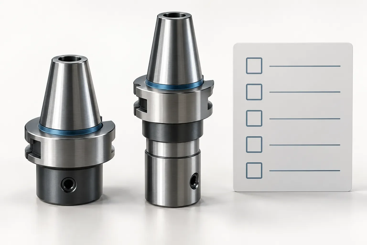
Tool holder adapters should be selected by the two interfaces they connect and the position of the resulting assembly. A matching description at one end does not resolve the other end, and an adapter should not be treated as a universal fix for an incompatible holder.
This guide uses two listed VDI Morse taper adapter configurations to show how to keep both sides identifiable. The examples provide named catalogue fields, not a complete fit approval or installation procedure. The corresponding drawings remain necessary to locate each feature physically.
Describe the two connections before choosing a model
Record the machine-side or holder-side interface that must receive the adapter. Then identify the tool-side connection and the actual tool being proposed. Keep the component names separate so that an enquiry does not confuse the adapter with the tool it is intended to support.
The cited adapter family is described as a VDI turret and tang-type Morse taper application. That description identifies the context of these products. It does not establish compatibility with every turret or every tool carrying a related interface label.
If replacing an adapter, record the complete designation and any readable identification on the installed assembly. Include the orientation and the surrounding holder arrangement rather than relying on an isolated picture of the component.
Compare two separately documented taper options
The F30-MT1 adapter and F30-MT2 adapter have different recorded MK values. Their selected dimensions also show why a shared d1 value is not a complete description.
| Recorded field | F30-MT1 | F30-MT2 |
|---|---|---|
| Diameter d1 | 30 mm | 30 mm |
| MK | 1 | 2 |
| Diameter d3 | 68 mm | 68 mm |
| Diameter d4 | 12.065 mm | 17.78 mm |
| Height h1 | 28 mm | 28 mm |
| Length l1 | 27 mm | 36 mm |
When a field is absent from a particular configuration, leave it unresolved rather than copying a value from the other option. Identify the missing feature before relying on the comparison. The table retains the source field names. It does not relabel d4 as a particular contact diameter or convert l1 into overall reach without the drawing establishing that meaning. The MK entries are recorded designations, not millimetre lengths.
A shared 30 mm d1 does not prove that the tool-side connection, installed position or complete assembly is the same. Keep the exact taper option and its drawing attached to the configuration being reviewed.
Review the assembled position and occupied space
An adapter adds another component to the tooling arrangement. Review the complete assembly with the actual tool, including the required working position and the surrounding space. The adapter's individual dimensions do not establish the assembled tool reach by themselves.
Show the relevant machine surfaces, workpiece and nearby tooling in the setup sketch. Explain any restricted approach or withdrawal area. No universal clearance value or collision-free motion follows from the selected table fields.
If an alternative adapter is proposed, compare its own dimensions rather than assuming that a change in taper designation leaves every other feature unchanged. The two cited records already demonstrate that one length field differs between the options.
Obtain installation and retention information
The configuration review should establish the applicable retention and installation requirements from the relevant documentation. Do not infer them from a photograph, a model suffix or the apparent shape of a taper.
Any tightening value, allowable load or operating restriction must be supported for the selected component and assembly. The dimensional record does not provide those properties, and this guide does not supply substitutes for them.
The same boundary applies to coolant and accessories. State the required provisions and request configuration-specific information. A commercial quotation should identify which adapter and additional items are included rather than treating an illustration as a package list.
Keep the connection record traceable
Prepare an enquiry with the adapter designation, both mating interfaces, actual tool identification, machine context, required position and quantity. Attach the relevant drawings and identify any unresolved interface feature precisely.
The tool holders and adapters catalogue can help locate candidate forms. Retain a separate configuration record for each proposed option and note the drawing revision where available. A useful adapter enquiry explains both what must connect and where the resulting tool must work; it does not stop at the interface name that first led to the product search.
Frequently asked questions
Do matching d1 values establish the same adapter assembly?
No. The tool-side option and other dimensions must also be compared using the actual drawing.
Are MK entries dimensions in millimetres?
The cited records use MK as a designation field. Do not treat its values as millimetre lengths.
Can the adapter record establish overall tool reach?
Not alone. Review the adapter together with the receiving holder, actual tool and required working position.