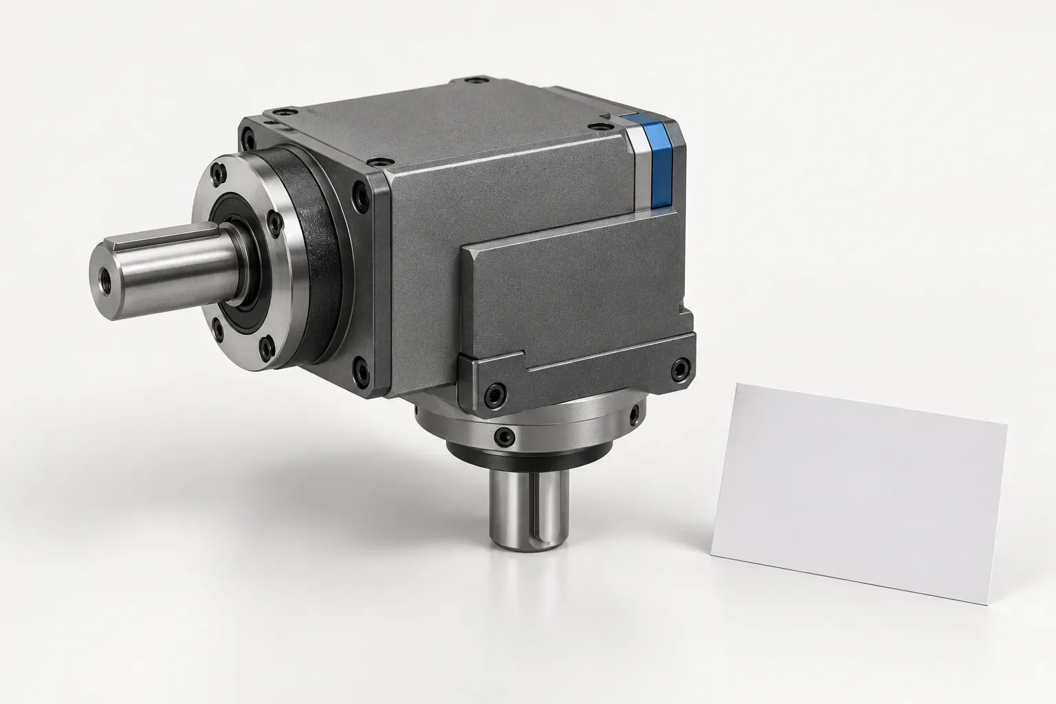
A right angle milling head enquiry should show the required cutter axis and the space available for the complete assembly. A right-angle arrangement changes tool direction, but the name alone does not establish cutter position, rotation direction, reach or machine compatibility. A drawing-based review is needed before a particular attachment can be treated as a candidate.
This guide focuses on orientation and working-envelope communication. It is not a product specification, a machining program or a claim that a particular head can complete the job. Use it to identify the geometry questions that the attachment and machine documentation must answer.
Draw the required cutter axis in the workpiece setup
Provide the part drawing and identify the feature to be milled. Show the intended cutter-axis direction relative to the machine spindle and the workpiece. A right angle means perpendicular directions, but an installation still needs a defined orientation around the machine spindle.
A photograph can communicate context, especially where access is restricted, but it should not replace the relevant drawing views. Mark the surface to be reached and any obstruction affecting approach. Do not assume that a general right-angle product image shows the same orientation as the actual job.
The distinction between axis direction and rotation direction is also important. Describing a perpendicular axis does not establish which way the output spindle turns or which cutter arrangement is appropriate. Those details belong to the instructions for the exact attachment and the selected cutting tool.
Separate attachment geometry from cutter projection
The head body, output interface, toolholder and cutter are separate parts of the installed envelope. Record each known component and retain its drawing datum. Do not use one catalogue length as a substitute for the cutter-tip position or the clearance needed around the assembled tool.
A longer cutter projection may change the space occupied by the assembly, but this guide does not establish an allowable projection or a machining limit. Obtain the relevant attachment and cutter documentation. An illustration cannot provide a safe maximum merely because the projected geometry looks plausible.
If the required position is not established by the available drawings, mark that as an unresolved item. Avoid creating a reach or clearance number from dimensions measured in a representative image. A precise-looking result does not make an undocumented geometric assumption valid.
Review the approach, cutting and withdrawal positions
Show how the proposed assembly is intended to approach the feature and leave it. Include the workholding, adjacent part surfaces and any nearby tool or machine obstruction that affects the envelope. The body can occupy space outside the immediate cutting region, so the feature view alone may be insufficient.
Keep this review distinct from programming. A purchasing guide does not establish machine offsets, collision-free motion or an approved operating sequence. The responsible machine and process review must evaluate the actual setup with the correct models and instructions.
Likewise, a right-angle label does not prove that every side face is accessible without repositioning the workpiece. The attachment and workpiece geometry must answer the specific access question. Do not turn the general purpose of an angle head into a guarantee about an unreviewed part.
Verify the interfaces and orientation arrangement
Request the machine-side interface drawing and the information that establishes attachment orientation. Include any required locating, stop or anti-rotation arrangement specified by the exact design. A suitable cutter-side holder does not establish that the attachment can be installed in the proposed spindle.
The manufacturer overview used as conceptual background distinguishes fixed-angle and adjustable arrangements. That distinction helps describe the requirement, but it does not establish the interfaces or instructions of an unrelated head. Preserve the proposed product identity when requesting those documents.
This guide provides no speed, torque, gear ratio, coolant pressure or fastening value. Obtain the limits that apply to the actual attachment and cutting assembly rather than borrowing data from another product with the same nominal direction.
Use an orientation-and-envelope enquiry sheet
| Drawing question | Information needed |
|---|---|
| Which feature is reached? | Identified workpiece surface or feature |
| Which way does the cutter axis point? | Axis shown in relevant drawing views |
| What occupies the working space? | Head, holder and cutter envelope |
| How is orientation established? | Exact locating and installation documentation |
| What is being supplied? | Head, adapters, holder and accessories identified |
The tool holders and adapters category supplies navigation context, while the contact page provides the enquiry route. These links do not verify a particular head or installation.
Send the drawing sheet, machine details, workpiece material, intended cutter and quantity together. Ask the quotation to identify the proposed configuration and answer the marked geometry questions. Retain the accepted drawings and operating documents with the purchase so that a right-angle description cannot be mistaken for a complete installation specification.
Frequently asked questions
Does a right-angle description establish cutter rotation direction?
No. Axis direction and rotation direction are separate information. Use the instructions for the exact attachment and cutter arrangement.
Can a head photograph establish usable reach?
No. Verify the component datums, cutter position and complete assembly envelope using the applicable drawings.
Does this guide prove that an angled feature can be machined without repositioning?
No. That depends on the actual attachment, part, workholding and machine setup, which require a specific review.