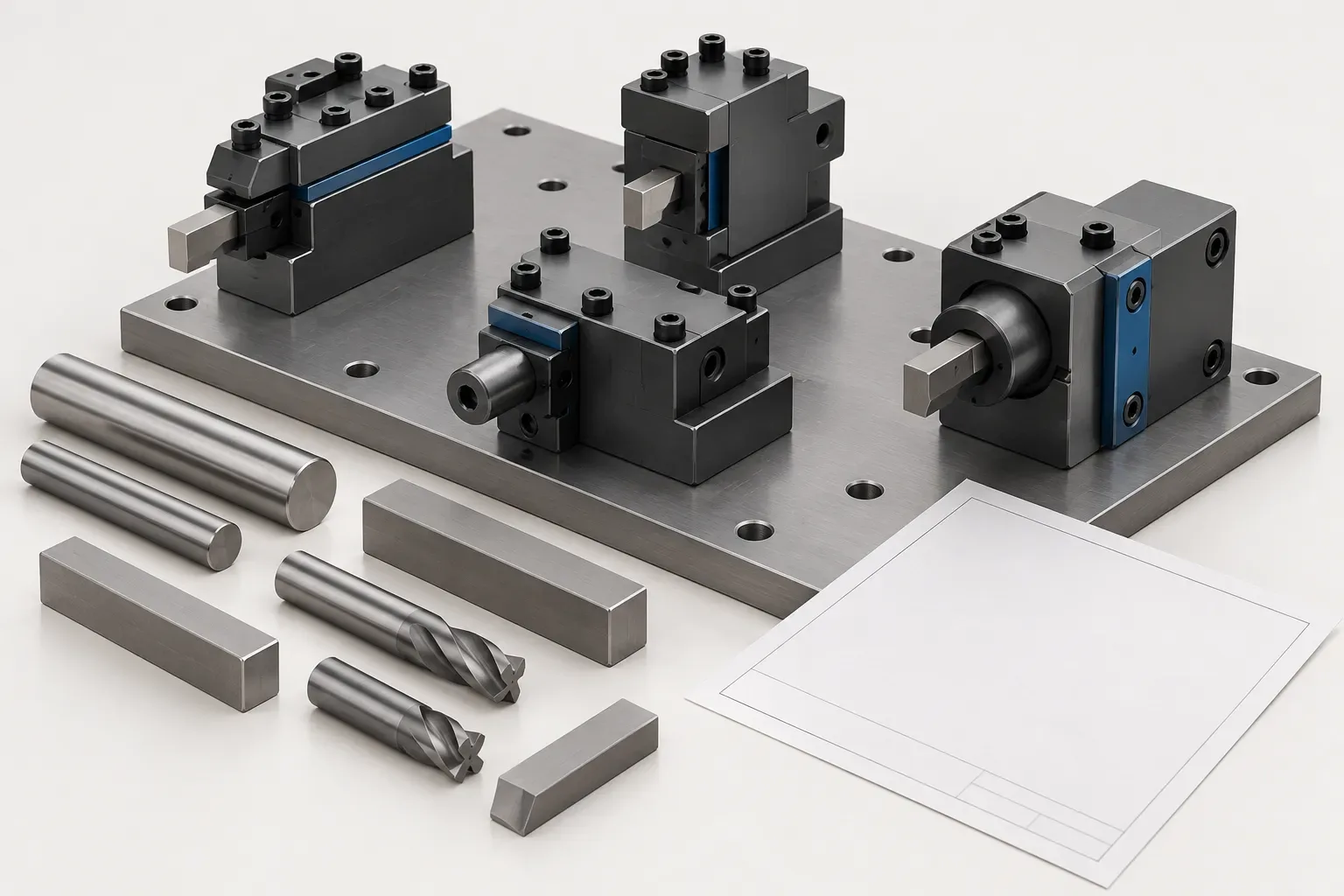
Gang tool holders should be selected as part of a complete tool layout. The individual holder must match its mounting requirements and cutting tool, but it must also occupy a usable position among the other tools in the setup. A holder that looks suitable by itself may still create an unresolved tool-position or space question once the layout is assembled.
This guide explains how to prepare that layout information for an enquiry. It uses two documented holder configurations to show why tool section and centre height should remain separate fields, without prescribing a machine arrangement or a collision-free program.
Begin with a list of operations and tool positions
Identify the operations that the layout must support and the cutting tool required at each position. Record the intended working direction and the workpiece features that constrain access. Keep each tool position identifiable on the setup sketch so that an enquiry can refer to a specific station in the arrangement.
The purpose is to describe the required layout rather than to select every holder from a catalogue photograph. A photograph can show general form, but it does not establish mounting compatibility, working position or the clearance required by a machine motion.
When replacing one holder within an existing arrangement, include the surrounding tools in the record. The replacement question concerns the space available in that setup, not simply whether the new component resembles the old one.
Separate tool section from centre height
The documented 39 mm centre-height gang holder records a 16x16 mm square tool section and a 39 mm centre height. The 40 mm centre-height configuration also records a 16x16 mm square tool section, but its centre height is 40 mm.
The selected fields below are specific to those configurations. They should not be treated as a standard dimension set for every gang-tool holder.
| Recorded feature | First configuration | Second configuration |
|---|---|---|
| Centre height | 39 mm | 40 mm |
| Square tool section | 16x16 mm | 16x16 mm |
| Base height A | 23 mm | 24 mm |
| Tool-mounting dimension K | 35 mm | 35 mm |
| Overall dimensions | 150x76x40 mm | 150x76x40 mm |
A shared square tool section does not resolve the height requirement. The actual tool position must be compared with the machine and setup references. Do not assume that the two examples can be adjusted into the same position merely because their overall dimensions agree.
Draw the mounting arrangement as well as the tool
Show the available mounting surface and the features used to locate and fasten the holder. Keep the relevant machine drawing or measured sketch with the enquiry. The selected holder's documentation must establish how those features relate to its tool position.
The two cited records list a mounting centre distance of 38–65 mm. That is the named field in those records; it should not be relabelled as a centre-height adjustment range or a tool travel. If the meaning of a feature is uncertain, identify it on the drawing instead of assigning a more convenient interpretation.
Installation torque, fastener selection and acceptable mounting conditions are separate requirements. Obtain the applicable instructions rather than deriving them from a mounting distance or outside dimension.
Check the layout with every cutting tool installed
The working envelope includes the holder, the tool clamping region and the intended tool projection. Review the adjacent tools, workpiece and chuck in the actual arrangement. A shortened product table cannot establish that all intended movements are clear.
Explain any restricted approach or withdrawal path using the part and setup drawings. The amount of space required depends on the complete application. This guide does not specify a universal clearance, tool spacing or motion sequence.
Do not infer cutting accuracy or rigidity from the holder dimensions. If a particular load or performance limit matters, request evidence applicable to the actual tool assembly and operating conditions.
Send one coherent layout enquiry
Provide a marked-up layout, the individual cutting-tool details, mounting information, required positions and quantity. Identify which holder configuration is being considered for each position and keep unresolved questions visible.
The tool holders and adapters catalogue can help locate candidates. Ask the quotation to distinguish holders from any tools, fasteners or accessories requested separately. Retaining the whole layout with the selection record makes it easier to assess a proposed alternative without losing the context that made the original holder useful.
Frequently asked questions
Does a 16x16 mm tool section determine holder centre height?
No. The cited configurations share that tool section but record different centre heights of 39 mm and 40 mm.
Is mounting centre distance the adjustment travel?
The cited record labels it mounting centre distance. It must not be relabelled as travel or a centre-height adjustment range.
Why include neighboring tools in an enquiry?
Their installed positions help define the available working envelope. An isolated holder image does not establish the space needed by the complete layout.