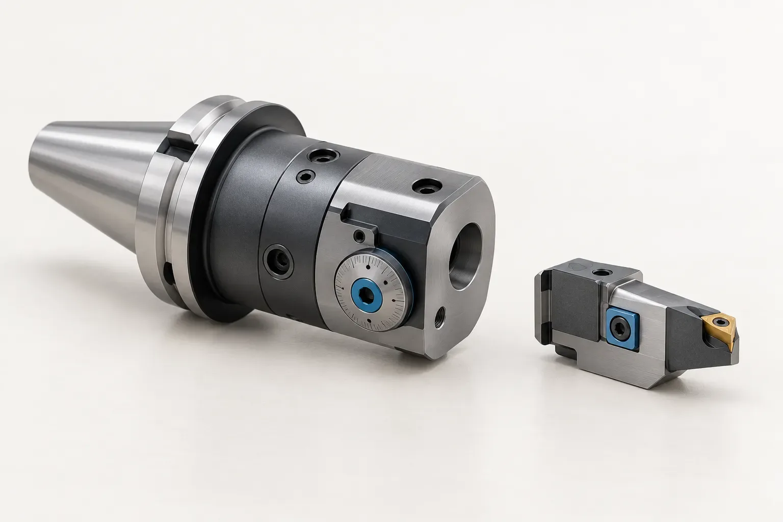
Fine boring heads should be selected from the required finished bore, the mating interface and the complete cutting assembly. A published diameter range is useful for screening candidates, but it does not describe every cartridge combination, prove a tolerance capability or establish machine compatibility. Keep those decisions separate before comparing products or requesting a quotation.
This guide uses two documented head configurations to explain the selection process. Their dimensions are specific to those records. They are examples of how to organize a finishing-tool enquiry, rather than a universal specification for all fine boring heads.
Define the finished feature before choosing the head
Record the required bore diameter, its tolerance, the usable depth and the relevant workpiece material. Include whether the feature is blind or through, and identify any shoulder or obstruction affecting access. The supplier needs the actual part requirement; a statement such as “precision boring” does not define an inspection criterion.
Separate the required final size from the condition of the existing hole. Explain which operation produces the incoming bore and what condition reaches the finishing stage. Do not assume that a head's stated coverage determines the amount of material it can remove in a particular application. Cutting conditions and the complete insert specification remain separate decisions.
Compare body geometry and interface dimensions
The fine boring head with a 30.9–40.1 mm range lists the following dimensions. Here, the pilot is a measured dimension; the connection designation identifies a system size.
| Recorded feature | Value |
|---|---|
| Boring diameter range | 30.9–40.1 mm |
| Pilot / shank diameter | 18.0 mm |
| Connection designation | 18 |
| Body diameter | 30.0 mm |
| Body length | 40.0 mm |
| Overall length | 51.75 mm |
Compare the mating drawing with the complete interface, not merely the number 18. Also check the body envelope and the space available for the assembly to approach and leave the feature. Body length, overall length and usable bore depth are different descriptions; they must not be substituted for one another.
Treat a wide range as an assembly question
The fine boring head with a 36.0 mm pilot is listed for 66.9–125.1 mm. Its record also divides that coverage into three working ranges with matching cartridges: 66.9–87.1 mm, 84.9–105.1 mm and 104.9–125.1 mm.
That distinction matters when preparing an order. The broad range is not evidence that a single unspecified cartridge covers every diameter. Identify the intended bore first, then ask for the cartridge configuration supporting that size. Where ranges overlap, the overlap provides candidates for checking; it does not select the correct assembly automatically.
For this head, the body diameter is 64.0 mm, body length is 71.0 mm and overall length is 107.0 mm. Those values describe the listed head. A separate shank or another component can change the complete installed envelope, so retain an assembly drawing in the enquiry rather than calculating reach from one isolated length.
Specify the cartridge, insert and coolant scope
A head record and a cartridge record answer different questions. The head establishes the supporting body and interface. A cartridge record can identify the insert family and its own working range. Neither should be treated as proof that the quotation includes every component shown in an illustration.
Ask the seller to identify the selected head, cartridge, insert designation and any shank or accessory separately. An insert-family code without its grade and nose-radius suffix does not establish suitability for a named material or finishing requirement. Do not infer an accuracy rating, surface-finish value, maximum speed or tool life from the words “fine boring.”
Both head examples specify through-tool coolant. That is a useful assembly feature to record, but it does not establish coolant pressure, flow, connection compatibility or a suitable machine setting. Those details require the applicable tooling and machine documentation. Keep any unresolved installation requirement visible before ordering.
Build a configuration record for quotation
Use the boring tools catalogue to identify candidates, then prepare a short configuration record containing the part drawing, required finished diameter, depth, material, quantity and machine interface. Include the head's complete identity and the working range selected for the cartridge.
Add an inspection plan stating which result will be measured and how acceptance is defined. The purpose is to communicate the manufacturing requirement, not to claim that a catalogue dimension guarantees the result. Where installation or adjustment instructions are missing, obtain the instructions for the exact assembly before use.
A useful quotation closes the remaining scope questions: what is supplied, which components mate together, which insert specification applies, and which limits are documented. Keeping those answers tied to one configuration prevents a broad range, a shared interface number or a representative image from becoming an unsupported promise.
Frequently asked questions
Does a fine boring head range apply to every cartridge?
No. A broad head range may require different matching cartridges. Identify the working range and complete assembly for the intended bore.
Does connection designation 18 mean a universal 18 mm interface?
No. In the example the measured pilot is 18.0 mm, while 18 is the system designation. The full mating geometry must also match.
Is through-tool coolant a pressure specification?
No. It describes a listed feature, not pressure, flow or machine compatibility. Obtain those requirements for the actual assembly.