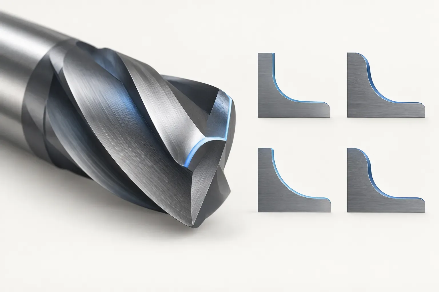
Corner radius end mills need two separate geometry checks: the cutter diameter and the specified corner radius. Neither value substitutes for the other. Select the complete profile against the part feature, then check cutting length, shank, material application and installation requirements. A radius label alone does not establish a performance improvement or a finished-part tolerance.
A useful enquiry keeps the radius attached to its unit and to the exact configuration. This guide uses documented metric and inch examples to show how radius information can be read without treating visually similar cutters as interchangeable. It does not prescribe an allowable engagement, cutting speed or edge-life expectation.
Start with the corner requirement on the part
Identify the feature that makes a radiused cutting profile relevant. Show the required corner geometry on the part drawing or a marked sketch, together with any tolerance that affects selection. Do not let a catalogue photograph become the only description of the required corner, because it cannot reliably establish a numerical radius or its tolerance.
Keep the tool radius and the part requirement as separate records until the machining plan has been reviewed. A cutter with a listed radius is a candidate for a process, not proof that every toolpath and setup will produce the required feature. The enquiry should also explain access restrictions and any geometry that must remain clear.
Read a metric radius configuration
The 8 mm four-flute corner-radius end mill has these confirmed fields:
| Recorded field | Value |
|---|---|
| Cutting diameter (DC, mm) | 8 |
| Corner radius (RE, mm) | 0.5 |
| Length of cut (LOC, mm) | 12 |
| Overall length (OAL, mm) | 58 |
| Shank diameter (DMM, mm) | 8 |
| Number of flutes (NOF) | 4 |
| Coating | Hybrid AlCrN |
Its 0.5 mm radius is not a second description of the 8 mm cutting diameter. Both are independently needed to identify the profile. The 12 mm cutting length and 58 mm overall length describe further aspects of the same configuration; they should not be replaced by lengths from another member of the family.
The listed shank form is Weldon. Match the shank form and diameter with the actual holder and installation instructions rather than assuming that a radius cutter requires a particular holding system. Tool geometry and toolholding are related selection questions, but their requirements must be checked separately.
Keep inch radius data in its original context
An inch three-flute DLC-coated radius configuration lists a 0.5 inch cutting diameter and a 0.12 inch corner radius. It has 1.25 inch cutting length and 3 inch overall length, with a 0.5 inch smooth shank. These values identify that particular configuration, not a metric equivalent chosen by visual similarity.
The two examples also differ in coating, flute count and documented material group. The inch example identifies aluminum as its primary group; the metric example lists steel, stainless steel and cast iron. A radius comparison must not silently convert those different records into a claim that the cutters are direct alternatives for the same application.
Do not substitute a chamfer or an unspecified edge
A corner chamfer is a different description from a corner radius. When reviewing quotations, compare the corner-type field and any associated numerical value before comparing price or availability. A matching diameter does not resolve a change in end profile.
The same care applies when a product is described as square end. If an exact edge preparation or corner tolerance matters, request the relevant drawing. Do not fill an empty radius field with an assumed zero or convert a chamfer size into a radius. That would create a specification that the product record never established.
Evaluate reach without inventing a working limit
Record the depth that the cutting edges must reach and identify any shoulder, fixture or workpiece feature affecting access. Compare those requirements with the complete cutter-and-holder assembly. Overall length is not unrestricted usable reach, and listed cutting length is not a recommended cutting engagement for every job.
If the application needs cutting conditions, supply the workpiece designation, its relevant condition and the planned operation. Obtain a recommendation for the exact configuration. The radius, coating and flute count do not independently justify a universal feed, speed or tool-life claim.
Put radius selection into a clear purchase record
Use separate fields for cutting diameter, corner type, radius with units, cutting length, overall length, shank and documented material group. Add the required quantity and any unresolved tolerance question. This makes differences visible instead of hiding them in a shortened title.
Before approving a quotation, check that the dimensional table, tool description and any application recommendation all concern the same cutter. An illustrative image can help explain the subject, but the purchase specification should remain traceable to the selected product record and the applicable technical documentation.
Frequently asked questions
Is a corner radius the same as cutting diameter?
No. They identify different geometry fields and must be recorded separately with units.
Can I substitute a chamfer for a corner radius?
Not without reviewing the part requirement and process. A chamfer and a radius are different profiles.
Does a radius value predict tool life?
No. The recorded radius identifies geometry and does not establish a tool-life result or universal cutting conditions.