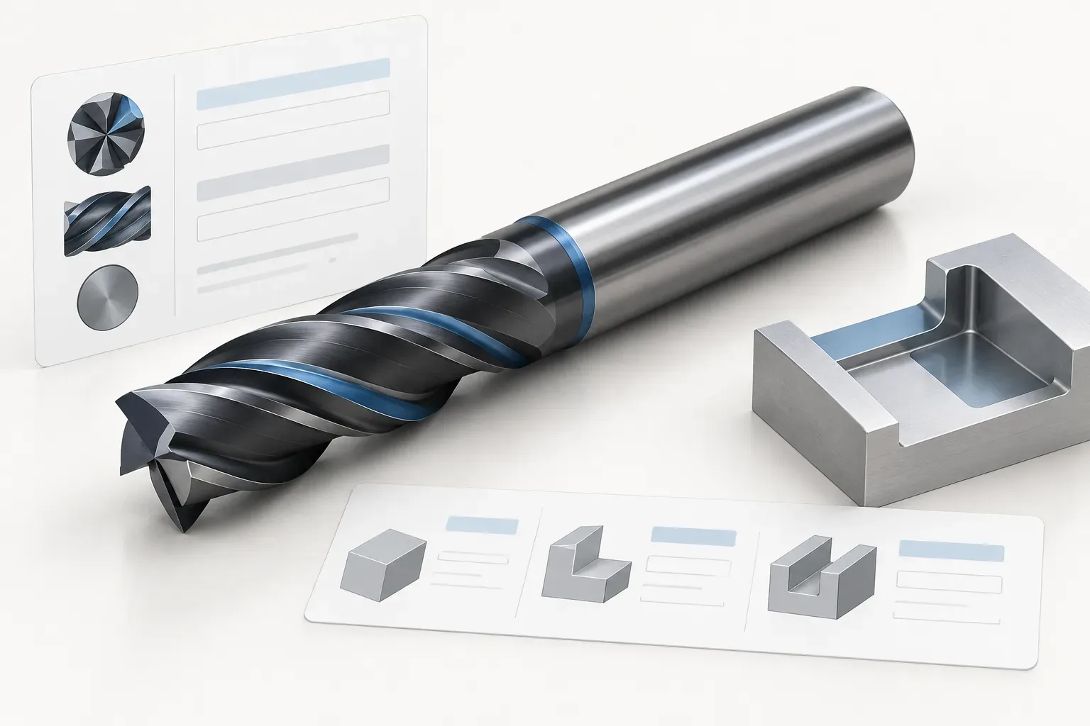
Carbide end mills should be selected as complete configurations: cutting profile, diameter, cutting length, shank, coating and documented workpiece group. A material label alone does not tell a buyer whether a cutter matches the part drawing or the toolholding arrangement. Begin with the feature that must be machined, then identify the dimensions and interfaces that actually control the selection.
This guide explains how to turn a broad enquiry into a comparable specification. Its numerical example describes one listed cutter, not a standard that applies to every carbide end mill. It does not prescribe cutting conditions, claim a tool-life advantage or establish that a named machine accepts the tool.
Define the feature before choosing the cutter
Write down whether the operation involves a shoulder, pocket, profile or another feature. Include the required corner form and the depth that the cutting edges must reach. The description should distinguish the part requirement from the proposed cutter: a drawing requirement is something the tool must help satisfy, not evidence that a particular listing will achieve it.
Next record the workpiece material and its relevant condition, the machine, the holder and any access restrictions. These details help a supplier identify unanswered application questions. They also prevent a quotation from becoming a comparison of diameters while the cutting length, shank or end geometry remains different.
Read one product row without mixing configurations
The 8 mm four-flute corner-radius cutter provides a useful configuration example. Its confirmed fields include:
| Recorded field | Value |
|---|---|
| Tool material | Carbide |
| Cutting diameter (DC, mm) | 8 |
| Shank diameter (DMM, mm) | 8 |
| Length of cut (LOC, mm) | 12 |
| Overall length (OAL, mm) | 58 |
| Number of flutes (NOF) | 4 |
| Corner radius (RE, mm) | 0.5 |
| Coating | Hybrid AlCrN |
Those values belong together. The cutting diameter and shank happen to be equal in this example, but that is not permission to assume equality on another cutter. Similarly, cutting length describes a different feature from overall length. Use the actual holder and setup drawings to determine how the stated dimensions relate to the intended assembly.
The product identifies steel, stainless steel and cast iron as primary workpiece groups. That statement is not a universal claim for every carbide cutter, nor does it establish a cutting speed for every alloy in those groups. Preserve the distinction between a documented application group and an application-specific recommendation.
Separate end geometry from coating
The catalogue includes square, corner-radius and chamfered-corner configurations. Choose the corner form by comparing it with the part geometry and the planned operation. Do not substitute a chamfer size for a corner radius merely because both appear near the cutting edge in a photograph.
Coating is another field in the configuration. It should not replace the geometry check or the documented workpiece group. Two cutters can share a coating name while differing in diameter, flute count, corner form and shank. A coating label by itself does not prove equivalent performance, a permitted temperature or a suitable feed rate.
Match the shank and assembly requirements
The example uses a Weldon shank. Its shank diameter is a starting point for identifying a suitable holder, but the holding arrangement must also match the shank form and the applicable instructions. Do not select a collet, tightening value or permitted overhang from the cutting diameter alone.
Check the cutter and holder together for reach and clearance. Record any shoulder or fixture that restricts the tool path. If a product listing does not establish the usable grip length or installation limit, obtain the relevant documentation instead of treating unused overall length as unrestricted working reach.
Compare offers using an explicit configuration record
A practical comparison sheet should place cutter diameter, cutting length, overall length, shank diameter and form, corner geometry, flute count, coating and material-group statement in separate columns. Keep the units visible. If one offer omits a field, mark it as unresolved in the purchasing record rather than silently copying the value from another offer.
The milling tools catalogue is a starting point for finding documented candidates. Compare the particular products rather than assuming a family picture represents every size. Where a source does not establish included accessories, ask whether the quotation covers only the cutter or a wider package.
Send the information needed for a useful quotation
Provide the part feature, workpiece designation, dimensions with units, intended operation, holder details and required quantity. Add the exact candidate configuration when one has been identified. If the drawing contains confidential details, a clearly marked feature sketch can identify the tooling question without turning an approximate sketch into a manufacturing specification.
Ask for the applicable application and installation information before treating a shortlisted cutter as approved for use. The commercial description, specification table and technical recommendation serve different purposes. Keeping them separate makes it easier to identify what is known, what is being requested and which configuration the final quotation actually covers.
Frequently asked questions
Does carbide identify a complete cutter specification?
No. It identifies the recorded tool material, while geometry, dimensions, shank, coating and application details still need to be specified.
Are LOC and OAL interchangeable?
No. LOC is the listed cutting length and OAL is overall length. Neither establishes a complete installation or clearance check.
Can I choose a cutting speed from this guide?
No. Obtain application-specific cutting information for the actual workpiece, cutter configuration and assembly.