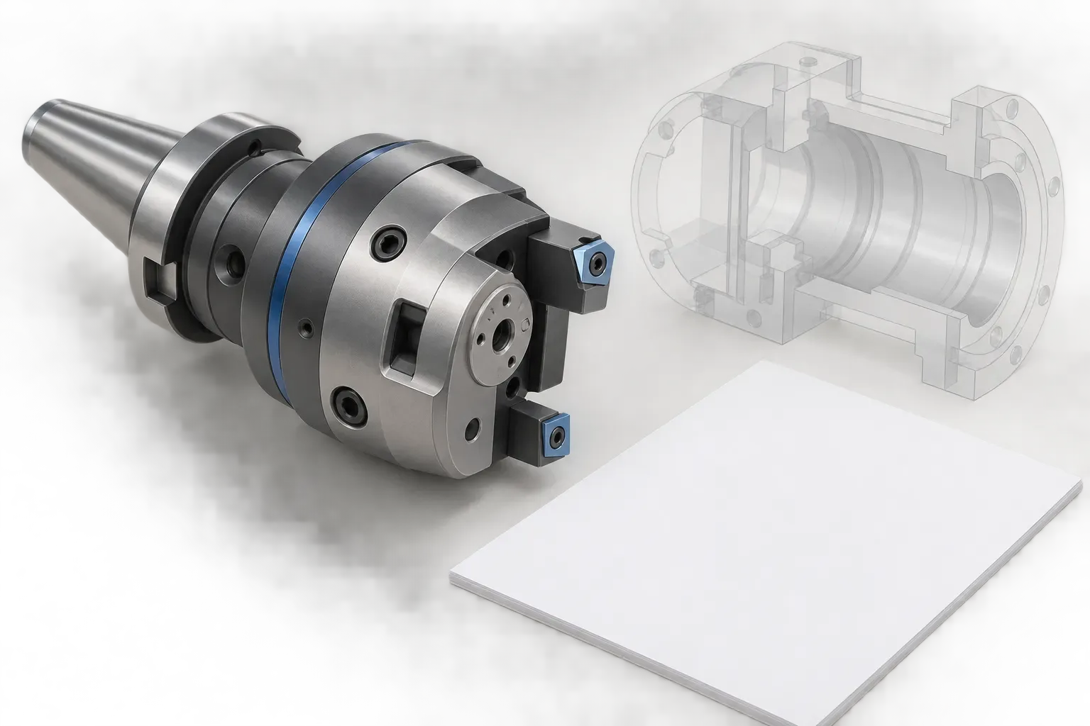
A boring head with a 46 mm pilot should be reviewed as part of the complete installed assembly, especially when the bore geometry imposes reach or clearance constraints. The pilot measurement narrows the search, but it does not establish usable depth, operating limits or the length of every component needed between spindle and cutting edge.
Two documented configurations make the distinction clear. They share a 46.0 mm pilot and a 90.0 mm body diameter, yet their operations, working ranges and lengths differ. A common body diameter therefore cannot stand in for a full configuration or installation check.
Define access and reach without inventing a depth rating
Send a part drawing showing the bore depth, shoulders, entry region and whether the feature is blind or through. Identify which surfaces restrict access and which tool position must reach the feature. Keep the feature dimensions separate from the tooling dimensions used to evaluate the assembly.
A head's body length and overall length are component measurements. Neither is automatically a maximum bore depth, an allowed overhang or the installed cutting reach. The complete tool can include other components, and the location of the cutting edge must be understood from the actual assembly drawing.
Where the available drawings do not establish the relevant position, mark the unanswered question. Do not create a reach value by subtracting or adding component lengths whose datums are not established. A numerical result is not useful if the geometry behind it has been assumed.
Compare the two recorded 46.0 mm pilot heads
The 86.9–154.1 mm fine boring head lists a 90.0 mm body diameter, 87.0 mm body length and 133.0 mm overall length. Its connection designation is 46.
The 115.0–156.0 mm rough boring head also lists a 90.0 mm body diameter and connection designation 46, but its body length is 105.0 mm and overall length is 123.0 mm.
| Recorded field | Fine-boring head | Rough-boring head |
|---|---|---|
| Pilot / shank diameter | 46.0 mm | 46.0 mm |
| Body diameter | 90.0 mm | 90.0 mm |
| Body length | 87.0 mm | 105.0 mm |
| Overall length | 133.0 mm | 123.0 mm |
| Boring diameter range | 86.9–154.1 mm | 115.0–156.0 mm |
Use the original drawing definitions when interpreting these lengths. The fact that one configuration has a longer body but a shorter overall length illustrates why the labels and datums matter. It does not establish a general geometric rule for all fine and rough heads.
Select the working interval before checking the cutting envelope
The fine-boring record lists working intervals of 86.9–116.1 mm, 104.9–134.1 mm and 124.9–154.1 mm with matching cartridges. The rough-boring record lists 115.0–136.0 mm and 135.0–156.0 mm. Identify the configuration supporting the required diameter rather than quoting only the broad head range.
This is also important for the envelope review. A body outline alone does not describe every cutting component or its position. Include the selected cartridge arrangement and any additional components in the drawing used to check the assembly.
The intervals can overlap, but overlap is not evidence of interchangeable cartridges, equal machining capability or identical installation instructions. Keep the operation and component identity attached to the selected interval so that different records are not combined into a fictional configuration.
Verify the mating system and coolant requirements
The system designation 46 should remain distinct from the measured 46.0 mm pilot field. Match the mating geometry and securing arrangement against the actual machine-side tooling drawing. A shared nominal dimension does not establish fit to an unspecified adapter or machine.
Both heads list through-tool coolant. Treat that as a feature to verify within the complete assembly, not as a pressure or flow specification. Request the applicable connection details and operating limits where they affect the setup. Do not infer them from a catalogue illustration.
Make the quotation answer the actual installation question
Use the boring tools catalogue to identify candidates and send the selected head, cartridge interval, feature drawing, material, interface details and quantity. State which shank, insert and accessories are requested and which items are already available.
Ask for the assembly information needed to resolve the marked access or fit uncertainty. Obtain the actual setting and installation instructions before use. A precise enquiry ties the proposed components to the geometry being checked; it does not replace that check with a claim that a 46 mm pilot guarantees sufficient reach.
Frequently asked questions
Do the two 46 mm pilot heads have identical lengths?
No. The documented fine head lists 87.0 mm body length and 133.0 mm overall length; the rough head lists 105.0 mm and 123.0 mm respectively.
Does overall head length establish maximum bore depth?
No. The installed assembly, cutting-edge position and feature access must be evaluated with the applicable drawing.
Can connection designation 46 prove fit to an adapter?
No. It identifies a system size. Check the measured pilot, mating geometry, securing arrangement and installation instructions.