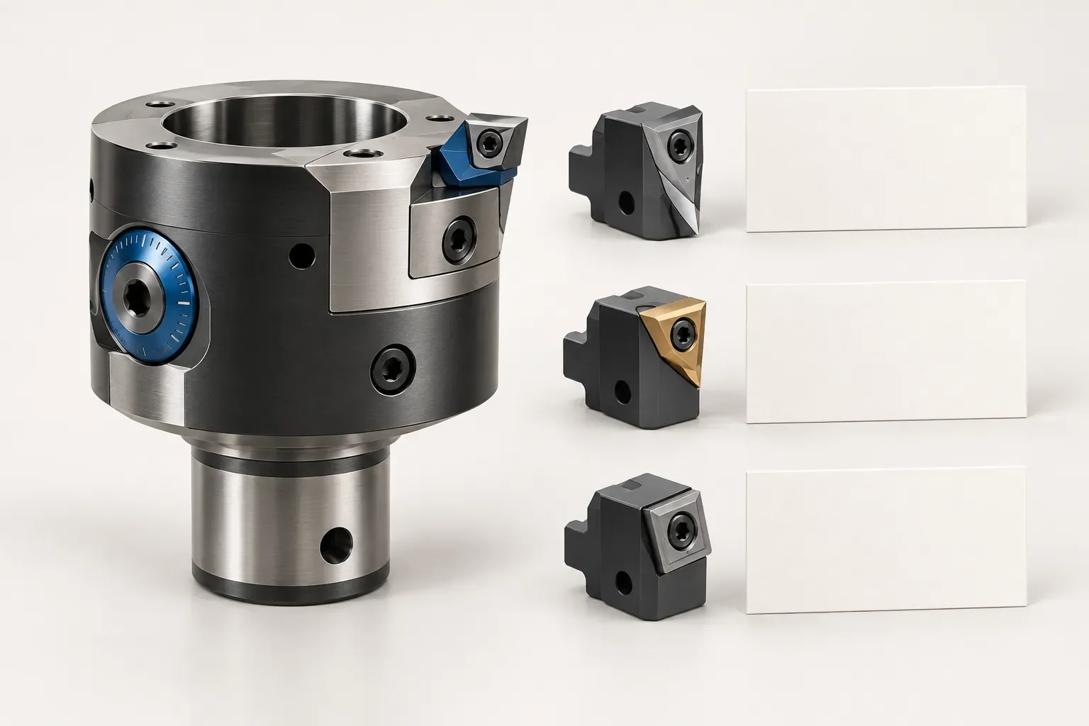
A boring head with a 36 mm pilot can represent several working configurations rather than one cartridge covering the full advertised range. For a multi-size job, map each required bore to the correct head and cartridge interval before deciding what to purchase. The measured pilot alone does not identify that coverage.
The documented examples below show why a configuration matrix is useful. The fine-boring head has three listed working intervals, while the rough-boring head has two. Those intervals belong to their respective cutting assemblies; they should not be mixed into a single generic range or treated as interchangeable parts.
Organize a multi-feature job before selecting components
List each bore feature from the part drawing and identify its operation, required diameter, depth and inspection requirement. Keep roughing and finishing in separate fields even when they concern the same physical feature. Record the workpiece material and any access constraint affecting the installed tool.
Next, create a candidate-configuration column for each feature. Its purpose is to identify a head and cartridge combination for review, not to assert that every candidate already satisfies the application. A feature list prevents the broad range in a catalogue heading from becoming an assumption that one unspecified package covers the entire job.
Read the fine-boring head's interval structure
The 66.9–125.1 mm fine boring head lists a 36.0 mm pilot and connection designation 36. Its body diameter is 64.0 mm, body length is 71.0 mm and overall length is 107.0 mm.
The product record divides its working coverage into 66.9–87.1 mm, 84.9–105.1 mm and 104.9–125.1 mm with matching cartridges. A required diameter must be related to the selected interval and the actual component identity. The broad head range does not establish that one unspecified cartridge supports every position within it.
The corresponding documented fine-cartridge records also show why a shared connection designation is not a complete purchase description:
| Fine-cartridge range | Connection designation | Overall length |
|---|---|---|
| 66.9–87.1 mm | 36 | 41.14 mm |
| 84.9–105.1 mm | 36 | 41.13 mm |
| 104.9–125.1 mm | 36 | 41.33 mm |
The measured overall lengths are recorded for those specific cartridges. Do not erase their differences by copying a shared family value. The shared insert family TPGH1103 also does not establish identical mounting geometry or a complete insert grade.
Keep the rough-boring head on a separate configuration line
The 76.0–116.0 mm rough boring head lists a 36.0 mm pilot, 65.0 mm body diameter, 110.0 mm body length and 125.0 mm overall length. Its recorded cartridge intervals are 76.0–97.0 mm and 95.0–116.0 mm.
Although both heads list a 36.0 mm pilot and connection designation 36, their operations, body dimensions and working intervals differ. Do not transfer a fine-cartridge choice to the roughing assembly on the basis of a shared number. Resolve the complete mating geometry and approved configuration from the applicable drawings.
Use interval overlaps carefully
An overlap can make more than one configuration a candidate for a required diameter. It does not select the configuration, define an adjustment procedure or establish equal performance. Preserve both candidate identities until the drawing and application review resolves the choice.
For a job with several bore sizes, ask which components are required for each feature and which may be reused only after compatibility is established. Do not promise a universal combination to reduce the apparent number of items. A clear matrix can show shared components without inventing interchangeability between unrelated records.
Keep cartridge quantity distinct from insert and accessory scope. A record describing a cartridge or set does not establish that the head, shank, inserts and mounting parts are included. The quotation must state these items explicitly.
Verify the assembly and operating documentation
Review the selected body and installed tool envelope against the actual part and approach path. Component lengths do not establish usable bore depth or a maximum overhang. Both head examples list through-tool coolant, but pressure, flow and machine-side connection requirements remain separate checks.
Use the boring tools catalogue to locate candidates, then send the completed feature matrix, drawings, material, interface information and quantity. Request installation and setting instructions for each selected assembly. Retain the component identities with the quotation so that repeat orders reproduce a checked configuration rather than merely repeating the 36 mm pilot description.
Frequently asked questions
Does one cartridge cover the full 66.9–125.1 mm fine-head range?
That is not established. The record lists three working intervals using matching cartridges, which must be selected for the intended bore.
Can the rough and fine heads share cartridges because both list connection 36?
A shared system designation does not prove interchangeability. Match the complete mating geometry and the approved assembly configuration.
Are all connection-36 fine cartridges the same length?
No. The three documented examples list overall lengths of 41.14 mm, 41.13 mm and 41.33 mm for their respective ranges.