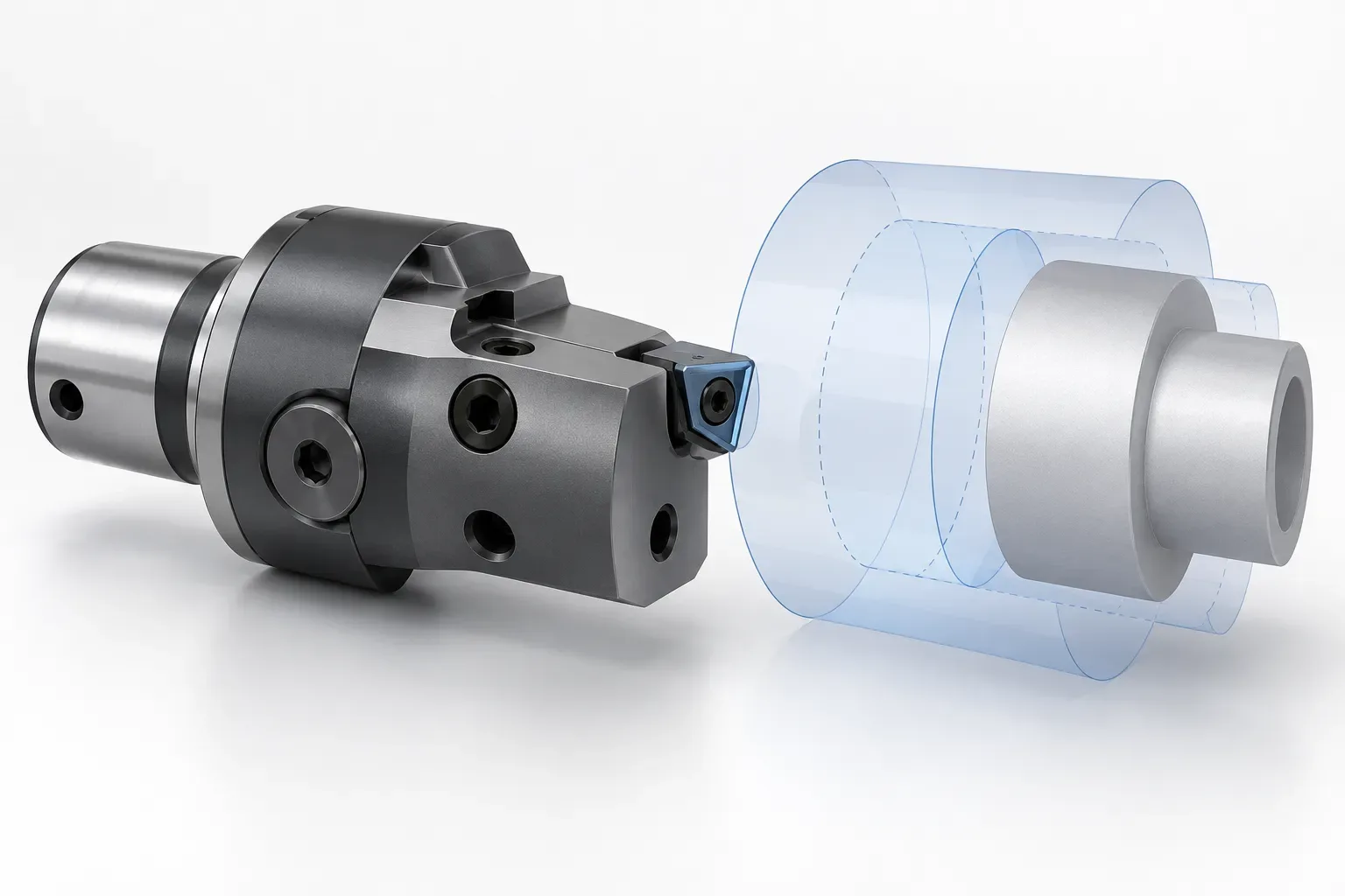
A boring head with a 22 mm pilot needs an envelope check as well as an interface check. In the documented examples, the pilot measurement is the same, but the head body diameters, lengths and working ranges differ. Selecting only by the mounting dimension can therefore leave the actual cutting-tool position and access requirements unresolved.
This guide concentrates on those geometry checks. The examples establish the dimensions of two specific heads. They do not establish a universal fit for a machine, a permitted bore depth or a guarantee that an assembly can pass a particular obstruction.
Separate the mounting measurement from the body envelope
The pilot is associated with how the head mates to another component. The body diameter and length describe different parts of the component envelope. The boring range describes cutting coverage when the appropriate assembly is used. None should be substituted for another merely because all are expressed as dimensions.
Begin with a drawing of the actual feature and the installed tooling arrangement. Identify the relevant datum, available approach space, shoulders and adjacent obstructions. Record which component dimensions are available and which aspects of the complete assembly remain unknown. This makes a geometry enquiry specific enough to check.
Compare the recorded head dimensions
The 39.9–51.1 mm fine boring head lists a 22.0 mm pilot, 38.0 mm body diameter and 47.0 mm body length. Its overall length is 67.0 mm and its connection designation is 22.
The 50.0–77.0 mm rough boring head lists the same 22.0 mm pilot measurement, but its body diameter is 42.0 mm, body length is 80.0 mm and overall length is 83.9 mm. Its connection designation is also 22.
| Geometry field | Fine-boring example | Rough-boring example |
|---|---|---|
| Pilot / shank diameter | 22.0 mm | 22.0 mm |
| Body diameter | 38.0 mm | 42.0 mm |
| Body length | 47.0 mm | 80.0 mm |
| Overall length | 67.0 mm | 83.9 mm |
| Boring diameter range | 39.9–51.1 mm | 50.0–77.0 mm |
These values show why the shared pilot is only a starting point. Do not take the differences between individual lengths as an undocumented projection or working-depth calculation. Use the original drawing views and the complete installed assembly to determine where each component sits.
Do not confuse cutting coverage with passage clearance
A stated boring range concerns the listed cutting configuration. It does not give a blanket clearance allowance for passing the complete tool through every feature of the part. Review the body and cutting components against the actual entry and withdrawal path rather than relying on the range alone.
For the rough-boring example, the record divides coverage into 50.0–64.0 mm and 63.0–77.0 mm working ranges with matching cartridges. Identify the selected interval before reviewing the final envelope. Different cutting configurations should not be represented by a single unverified outline simply because the supporting head is unchanged.
Keep the final diameter and the existing feature condition separate on the drawing. The geometry review should consider the assembly relevant to the planned operation, not an assumed finished opening that is unavailable at the start of the process.
Resolve the interface beyond the number 22
Connection designation 22 identifies a system size in these records. The measured pilot is separately listed as 22.0 mm. Those descriptions do not establish all the locating surfaces, fastening details or fit requirements. Compare the mating drawing and obtain the installation instructions for the exact assembly.
Photographs can support identification, particularly for an existing installation, but they cannot verify a hidden surface or an unmeasured dimension. Mark unresolved features on the drawing rather than assuming that a visually similar head supplies the missing geometry.
Both examples specify through-tool coolant. Retain that feature in the enquiry, while treating pressure, flow and machine-side connections as separate requirements. No coolant operating value is inferred here from the component dimensions.
Request an assembly-level response
Use the boring tools catalogue to identify the product records, then send the candidate head, required cutting range, part drawing, depth, material, machine-side interface and quantity. State which cartridge, insert, shank and accessories are intended to be included.
Ask the supplier to address the specific envelope or interface uncertainty shown on the drawing. Do not request a general compatibility assurance in place of resolving the actual surfaces and dimensions. Preserve any agreed assembly drawing with the quotation so that the eventual supplied configuration can be checked against the same geometry review.
Frequently asked questions
Is a 22 mm pilot the same as a head body diameter?
No. The examples separately list a 22.0 mm pilot and body diameters of 38.0 mm and 42.0 mm.
Does the boring range establish entry clearance?
No. Review the actual component and assembly envelopes against the incoming feature and planned tool path.
Can the body length be subtracted from overall length to infer usable reach?
Not without the applicable drawing definitions and assembly geometry. Do not convert isolated catalogue lengths into an undocumented depth rating.