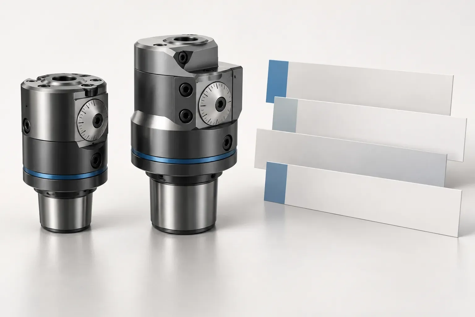
When selecting a boring head with an 18 mm pilot, compare the operation and cartridge coverage before treating the pilot as a complete product identity. The documented range includes an 18.0 mm pilot fine-boring configuration and an 18.0 mm pilot rough-boring configuration. Their ranges overlap in part, but the overlap does not make the two assemblies equivalent.
The practical task is to connect each head to its own role in the process. Keep the incoming feature, the required output and the cutting-component selection on the same configuration record. This avoids mixing a finishing requirement with a roughing assembly merely because both candidates share a pilot measurement.
State what the head must do to the existing bore
Describe the bore that reaches this operation, the diameter required after it and any later finishing step. Supply the feature depth, workpiece material and a drawing showing access restrictions. If a tolerance applies to the final part, identify which operation is responsible for meeting it.
Do not read an accuracy capability into the fine-boring designation or assume a material-removal allowance from the rough-boring designation. The relevant insert, assembly limits and process conditions are separate information. The head dimensions help identify candidates; they do not establish the complete machining method.
Read the fine-boring configuration independently
The 30.9–40.1 mm fine boring head lists an 18.0 mm pilot, 30.0 mm body diameter, 40.0 mm body length and 51.75 mm overall length. Connection designation 18 identifies its system size. Through-tool coolant is listed as a feature.
Keep each value attached to its label. The body diameter is not the pilot diameter, and overall length is not a statement of usable bore depth. When reviewing a replacement, compare those fields with the applicable drawing rather than trying to reconstruct the complete tool from its title.
Interpret the rough-boring coverage at cartridge level
The 34.0–51.0 mm rough boring head also lists an 18.0 mm pilot and connection designation 18. Its body diameter is 31.0 mm, body length is 60.0 mm and overall length is 64.8 mm.
Its working coverage is divided into 34.0–43.0 mm and 42.0–51.0 mm with matching cartridges. Those intervals matter when selecting the cutting components. A request stating only the broad 34.0–51.0 mm range does not identify which cartridge configuration supports the intended bore.
| Selection question | Fine-boring record | Rough-boring record |
|---|---|---|
| Listed overall range | 30.9–40.1 mm | 34.0–51.0 mm |
| Listed cartridge intervals | Matching cutting assembly required | 34.0–43.0 mm; 42.0–51.0 mm |
| Body diameter | 30.0 mm | 31.0 mm |
| Body length | 40.0 mm | 60.0 mm |
The table is a comparison of these records, not an interchangeability chart. Similar measured pilots and partially overlapping cutting ranges do not resolve the locating surfaces, fasteners, tool position or assembly instructions.
Keep overlapping ranges from creating a false substitute
A diameter within overlapping product ranges can be a candidate for more than one selection. The next question is which operation, insert and assembly are required, rather than which range contains the number first. A roughing head should not be offered as proof of a finishing capability that has not been documented.
Likewise, overlap between cartridge intervals does not establish identical envelopes or a common setting procedure. Identify the actual cartridge and use its record alongside the head drawing. Do not borrow an overall length, insert family or accessory package from the neighboring configuration in a catalogue.
Review installation as a complete assembly
Confirm the mating geometry against the machine-side tooling drawing and identify any adapter or shank required. Record the position of the cutting edge and the available approach space. A component-level length cannot establish that the installed tool can reach every surface shown on the part.
Both example heads list through-tool coolant, but neither value establishes pressure, flow or a machine connection. Installation limits, fastening values and adjustment instructions must come from the applicable documents. Keep these questions separate from the diameter table so that unanswered requirements remain visible.
Send one unambiguous configuration for quotation
Use the boring tools catalogue to identify the candidate, then send the selected head identity, working diameter, operation, depth, material, interface drawing and quantity. Specify the cartridge range and ask whether inserts, a shank and other accessories are included.
The quotation should describe the same assembly that the drawing review evaluated. Preserve the agreed component identities for later repeat orders. An 18 mm pilot is a useful search filter; a complete operation-specific configuration is the information needed to discuss a purchase accurately.
Frequently asked questions
Can an 18 mm pilot identify the correct head by itself?
No. The documented fine and rough heads share that pilot measurement but have different ranges and body dimensions.
Why does the rough head list two cartridge ranges?
Its broad coverage is supported by corresponding cartridge configurations. Identify the interval needed for the intended bore rather than assuming one unspecified set covers the whole range.
Does a shared cutting diameter prove equal capability?
No. The operation, insert specification, mating geometry and documented assembly limits must be evaluated separately.