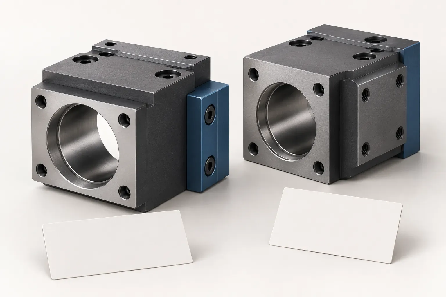
A BMT85 tool holder should be selected as a complete configuration rather than as a mounting label followed by an assumed bore option. Two documented BMT85 boring holders demonstrate why: they share the listed centre height and mounting-hole pitches, yet their recorded mounting-face dimensions are different.
This is a configuration-control problem as much as a dimensional one. When a buyer changes the required boring-bar diameter, the holder record must be checked again. Carrying the remaining dimensions across from the first option would misdescribe the second product.
Compare the two records without merging their data
The BMT85-B40-H85 boring holder lists a 40 mm tool bore. The BMT85-B60-H85 boring holder lists a 60 mm tool bore. Both identify A as an 85 mm bore centre height.
The selected fields below show where their dimensional records agree and where they differ. All values are specific to the named configurations; they do not define every BMT85 holder.
| Recorded feature | BMT85-B40-H85 | BMT85-B60-H85 |
|---|---|---|
| Tool bore diameter D | 40 mm | 60 mm |
| Overall front-view height B | 132 mm | 130 mm |
| Locating-slot width C | 25 mm | 25 mm |
| Horizontal mounting-hole pitch E | 100 mm | 100 mm |
| Vertical mounting-hole pitch F | 100 mm | 100 mm |
| Mounting-face width G | 124 mm | 125 mm |
| Mounting-face length H | 161.5 mm | 125 mm |
A shared centre height does not make the outside form identical. The recorded G and H differences must remain visible when reviewing the mounting face and the surrounding space. Do not correct an unexpected dimension by copying the value from the other configuration.
Use the drawing to identify a real discrepancy
If the record appears inconsistent with an installed holder or a machine requirement, identify the exact feature in question. Mark its drawing label, value, unit and reference view. A precise query preserves the evidence needed to resolve the issue.
An unexplained difference should not be turned into an interchangeability claim or a homemade dimensional standard. Request the relevant drawing or configuration clarification before ordering. That process is different from treating every listed field as a complete installation approval.
Photographs can help show which surfaces are being discussed, especially when replacing existing tooling. They cannot establish a mounting tolerance, internal feature or permitted modification that is absent from the documentation.
Keep the bar requirement tied to the selected option
Identify the boring bar and its actual clamping requirements separately from the holder. Record the required bore interface, intended projection and cutting-head arrangement. A compatible clamping system cannot be established simply by matching a nominal diameter.
The two examples do not establish an included sleeve or an interchangeable bar package. If a sleeve, fastener or other item is required, list it explicitly in the request. Ask the quotation to distinguish the holder from additional specified components.
Changing the bar requirement should trigger a fresh review of the holder configuration. This includes the mounting-face dimensions and the complete installed envelope, not just the bore row that prompted the change.
Review the assembly space without inferring performance
Show the part feature, chuck position and neighboring tooling relevant to the job. Review the intended approach and withdrawal conditions using the machine and assembly documentation. The holder table does not supply a universal clearance allowance.
Do not rank the two examples by presumed stiffness, capacity or cutting accuracy. Their recorded dimensions do not establish those performance outcomes. An operating limit must be supported by information applicable to the complete assembly and intended use.
The same applies to installation. Obtain the specified fastening and clamping instructions for the exact holder and bar arrangement. A mounting pitch is not a tightening value, and a similar outside shape does not prove that another product's instructions apply.
Keep a revision-ready enquiry record
Prepare a single configuration sheet containing the holder designation, required bore, tool position, machine and turret identification, quantity and drawing references. Include the individual G and H fields instead of describing both options as the same body with different bores.
The tool holders and adapters catalogue can support further comparison. Retain a separate record for each candidate and identify what changes when an alternative is proposed. This keeps an enquiry accurate when its starting assumption changes and reduces the chance of quoting one product using another configuration's dimensions.
Frequently asked questions
Can the mounting dimensions be reused when the bore changes?
Only where the selected configuration explicitly confirms them. The two cited BMT85 records have different G and H values.
What centre height do both examples record?
Both identify A as an 85 mm bore centre height. This agreement does not establish the same overall body dimensions.
What should I do with an unexpected dimension?
Identify the exact drawing field and request clarification. Do not replace it with a value copied from a similar configuration.