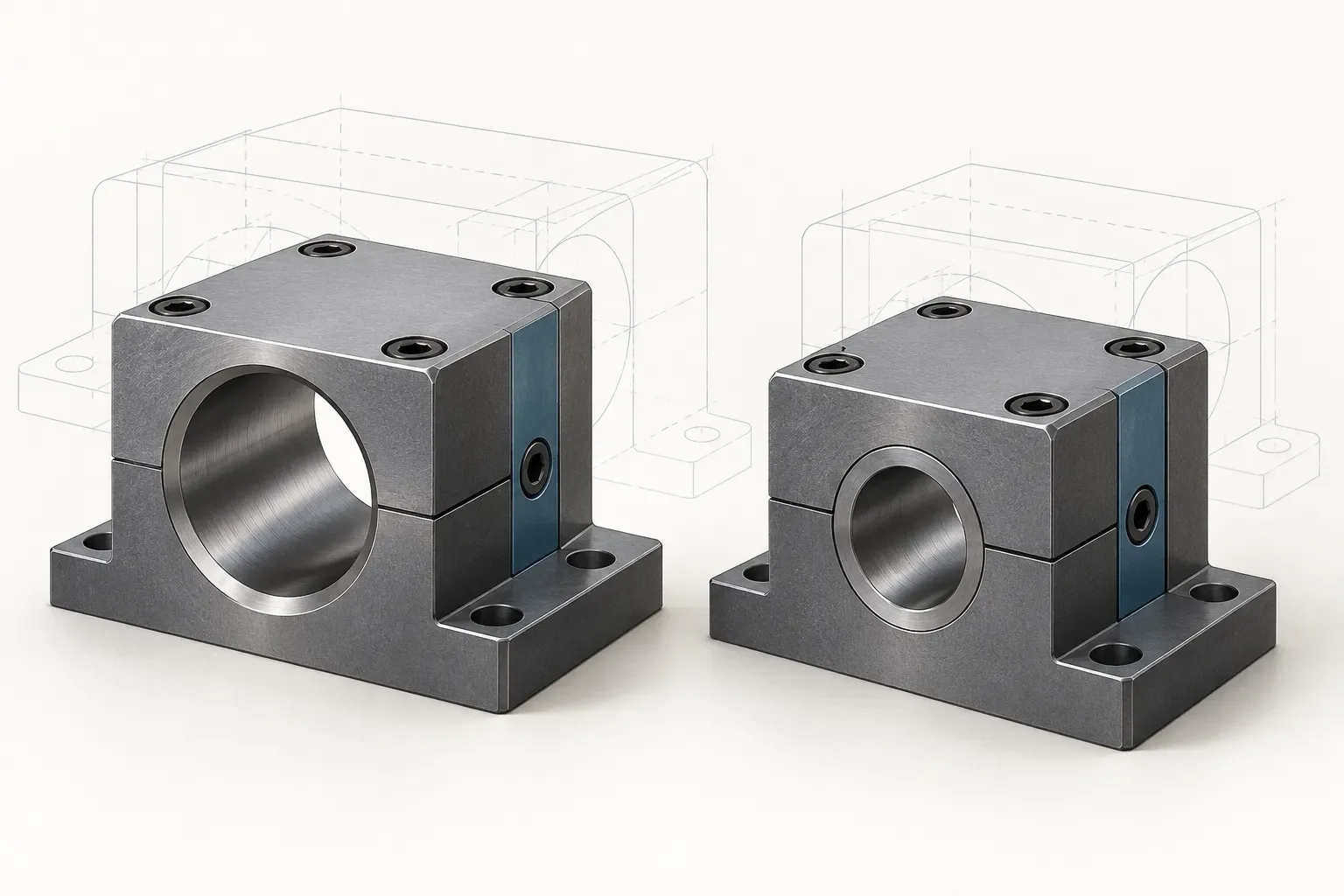
A BMT75 tool holder enquiry can involve two different size questions: the diameter of the tool bore and the space occupied by the holder body. Those questions should be checked separately. Two documented boring-holder configurations have the same recorded bore centre height and mounting fields, but different bores and different overall front-view heights.
This guide uses that pair to build an envelope review. It does not establish a standard body size for every BMT75 product, and it does not claim that a larger bore configuration is a machining upgrade. The required boring bar, its position and the available space decide what needs investigation.
Identify the two bore configurations precisely
The BMT75-B50-H90 boring holder lists a 50 mm tool bore D. The BMT75-B60-H90 boring holder lists a 60 mm tool bore D. In both records, A is a 90 mm bore centre height.
Their B fields differ: the 50 mm bore configuration has a 130 mm overall front-view height, while the 60 mm bore configuration lists 140 mm. Keeping that difference visible prevents a buyer from treating the two holder bodies as identical merely because their mounting rows match.
Select the bore from the documented requirements of the actual boring bar and clamping arrangement. The listing does not establish a reducing sleeve, permitted projection or assembly torque. Those questions must be resolved from the relevant tooling instructions rather than inferred from the bore dimensions.
Separate the mounting footprint from the body envelope
The following fields are shared by the two specific configurations in this comparison. They describe selected mounting features, not the complete outside shape or the installed assembly.
| Recorded mounting feature | Label | Listed value |
|---|---|---|
| Locating-slot width | C | 25 mm |
| Horizontal mounting-hole pitch | E | 90 mm |
| Vertical mounting-hole pitch | F | 90 mm |
| Mounting-face width | G | 112 mm |
| Mounting-face length | H | 120 mm |
Do not use mounting-face length as a substitute for tool projection or overall reach. A drawing can define several lengths for different purposes. Preserve the feature name and the view used to locate it.
Although the two pitch values are equal here, their directional labels still belong in the comparison. The actual turret drawing determines which mounting features must agree and whether the complete locating arrangement is suitable.
Evaluate the assembly rather than an isolated block
A holder envelope review should include the selected bar and any separately specified components. Show the intended bar projection and the workpiece feature that requires it. Identify nearby surfaces that could restrict the approach or withdrawal path.
The holder's outside dimensions cannot establish a collision-free machine motion. The chuck, workpiece, neighboring tools and setup orientation are part of that review. This article supplies no universal clearance allowance or machine-specific movement approval.
The greater front-view height of one listed configuration is a geometric difference, not a performance claim. It does not by itself prove a stiffness increase, a higher load rating or improved cutting results. Such statements require evidence for the complete assembly and application.
Keep purchase options independent of assumptions
If the required bar diameter is not represented by either example, request a separately documented option. Do not create another model by editing the bore number or assume that a suitable sleeve is included. A configuration change can affect more than the feature that prompted the enquiry.
Describe accessories as individual request items. A representative photograph may show the product family but does not establish the commercial package. Ask the quotation to identify exactly which holder, clamping items and requested accessories are covered.
For installation questions, retain the manufacturer's or supplier's applicable instructions with the configuration record. Mounting dimensions do not supply tightening values or inspection limits, and a visually similar holder's instructions are not a substitute.
Prepare an envelope-focused quotation request
Send the full holder designation, bar details, machine and turret identification, quantity and the relevant drawings. Mark the required bore position and any restricted working space. State whether a dimension is an installation requirement or a preference so that proposed alternatives can be reviewed honestly.
Use the tool holders and adapters catalogue to locate candidates, then compare the individual records. An effective BMT75 enquiry makes both interfaces and the surrounding envelope visible. That is more useful than asking for a broad size label while leaving the actual bar and space requirements undefined.
Frequently asked questions
Do the two BMT75 examples have the same overall height?
No. Their listed overall front-view heights are 130 mm and 140 mm, respectively, even though both record a 90 mm bore centre height.
Does the larger bore establish better machining performance?
No. Bore and body dimensions describe geometry. Performance requires evidence for the complete tool assembly and application.
Is the mounting-face length the tool reach?
No. The record labels H as mounting-face length. Required reach must be reviewed with the bar and complete setup.