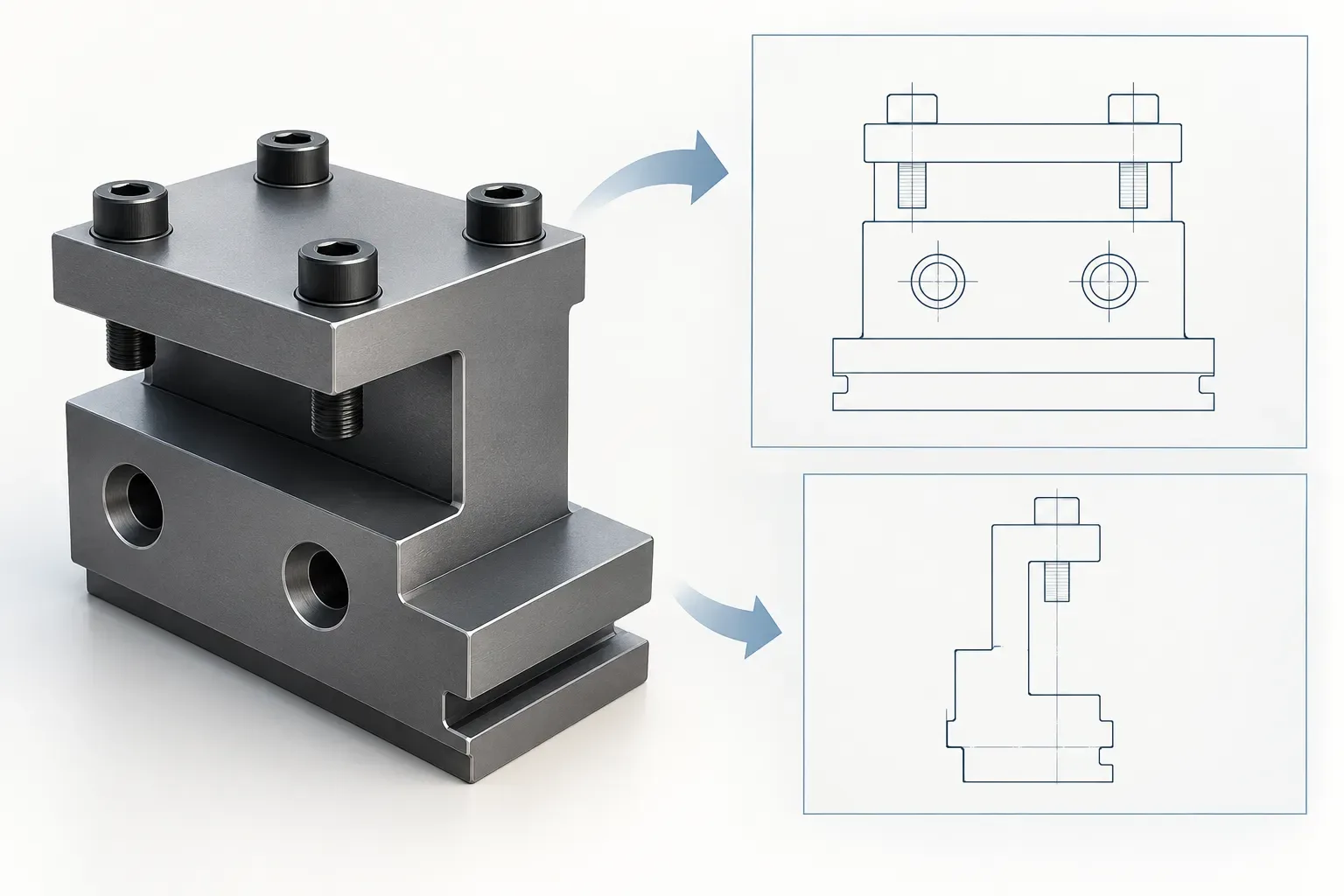
A BMT65 tool holder comparison needs more than a pair of mounting-pitch numbers. The direction assigned to each drawing label matters, and that assignment can change between holder families. Two documented BMT65 configurations show why a spreadsheet containing only letters and values can create a misleading replacement description.
The task in this guide is to compare mounting features without losing their meaning. It uses one boring holder and one external holder. They are different product forms, not alternative names for the same assembly, and no machine interchangeability is claimed.
Name the holder form before comparing its interface
The BMT65-B40-H72 boring holder records a 40 mm tool bore D and a 72 mm bore centre height A. Its overall front-view height B is 112 mm. The record identifies a BMT turret application.
The BMT65-C25-H80 external holder uses a different set of feature definitions. Its A field is a 30 mm lower-step height, and B is an 80 mm overall side-view height. These are not the boring holder's centre-height and front-view-height fields.
Decide which operation and tool arrangement is required before interpreting these values. A bore dimension cannot describe an external tool's clamping section, and an external holder's step height cannot be substituted for a boring holder's bore position.
Preserve the orientation of mounting-hole pitches
The following comparison reproduces selected named fields from those two records. It is intended to demonstrate label meaning, not to define a common BMT65 mounting standard.
| Field | Boring holder record | External holder record |
|---|---|---|
| Locating-slot width C | 18 mm | 18 mm |
| Horizontal mounting-hole pitch | E: 73 mm | F: 70 mm |
| Vertical mounting-hole pitch | F: 70 mm | E: 73 mm |
| Mounting-face width G | 97 mm | 97 mm |
| H definition and value | Mounting-face length: 126 mm | Overall plan-view length: 131 mm |
The numerical pair 73 and 70 appears in both records, but the stated orientations differ. That distinction must survive any enquiry or drawing comparison. Do not relabel the external record to make it look consistent with the boring record.
If a drawing view appears ambiguous, keep the original feature labels and mark the question for clarification. Rearranging the values to fit an expected pattern would conceal an unresolved interface issue rather than solve it.
Compare the actual turret drawing in the same view
Obtain the relevant turret-interface drawing and identify its reference surfaces. Match each required feature by its physical definition and direction. Where different views are used, show how the compared feature is being identified instead of relying on a model suffix.
Include locating geometry as well as mounting holes. A set of matching pitch values does not establish the complete mating arrangement or fastening requirements. The holder description also does not supply an approved bolt specification or installation torque.
For a replacement enquiry, label photographs with the installed orientation and the position of the tool relative to the workpiece. Photographs provide context, while dimensioned drawings establish the features being compared. Neither should silently replace the other.
Review the working side independently
Once the interface questions are clear, check the cutting-tool side of the assembly. For the boring configuration, identify the actual bar, its clamping region and the required projection. For an external configuration, provide the tool's own section dimensions and working direction.
Do not derive a complete clamping specification from the holder designation. The recorded external-holder dimensions do not establish a tool capacity simply because a number appears familiar. Likewise, the boring holder's bore does not prove a particular sleeve is included or suitable.
The assembled tool must also be reviewed for clearance around adjacent tooling, the workpiece and the chuck. Any permitted load, operating limit or accuracy requirement needs its own evidence; the selected table fields are geometric information only.
Keep an auditable comparison record
Create separate rows for the turret requirement, the proposed holder and the cutting-tool requirement. Use named features, units and drawing references rather than a compressed string of numbers. Identify any unanswered question before asking for a final configuration-specific quotation.
The tool holders and adapters catalogue can help identify other candidates. Retain the individual drawing definitions for each one. A useful comparison explains why a holder is being considered and what still needs verification; it does not manufacture a fit claim by making different drawings look alike.
Frequently asked questions
Why are E and F not interchangeable in a comparison?
The two cited drawings assign different orientations to those labels. Preserve each named feature and its drawing context.
Do the shared BMT65 label and slot width prove fit?
No. Complete locating, mounting and installation details must be compared with the actual turret documentation.
Can H be compared as the same feature in both examples?
Not directly. H is mounting-face length in the boring record and overall plan-view length in the external record.