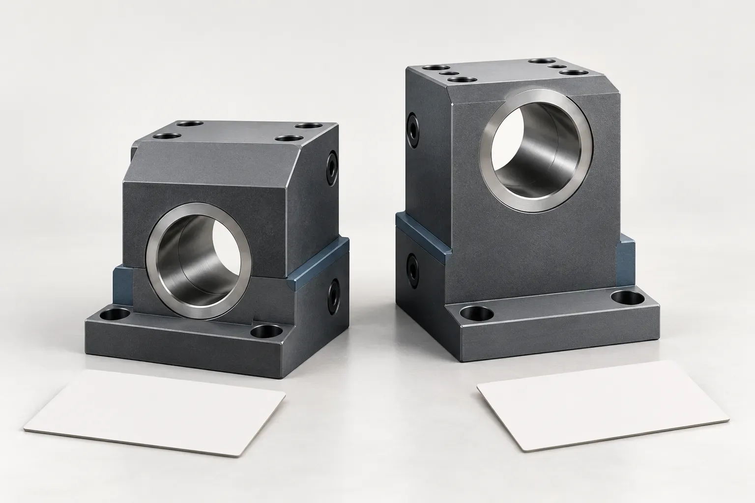
Selecting a BMT55 tool holder involves checking where the tool will sit, not just whether the tool can enter the holder. Two documented BMT55 boring configurations illustrate that distinction: both list a 32 mm tool bore, while their bore centre heights differ. A replacement decision therefore needs a positional requirement as well as a bore requirement.
This guide addresses that specific comparison. It does not assign machine compatibility from the BMT55 label or turn a height difference into an assumed adjustment feature. The examples are separate listed configurations, each with its own dimensional record.
State the required tool position first
Before comparing holders, identify the turret reference and the intended boring-bar position from the machine and setup documentation. Mark the relevant height on the drawing and show the direction in which it is measured. A height without a reference surface is difficult to compare reliably.
If replacing existing tooling, record the complete assembly before removing it. Identify any separate component actually used between mating parts. Do not assume that a visible difference in tool position is produced by the holder alone, or that an unlisted spacer can solve it.
The aim is to describe the required configuration rather than to prescribe a machine setup procedure. Tool positioning, fastening and any acceptance limits remain subject to the applicable machine and tooling instructions.
Compare two documented BMT55 height configurations
The BMT55-B32-H60 boring holder and BMT55-B32-H85 boring holder share several recorded fields, but they are not the same geometric option.
| Recorded feature | BMT55-B32-H60 | BMT55-B32-H85 |
|---|---|---|
| Bore centre height A | 60 mm | 85 mm |
| Overall front-view height B | 90 mm | 115 mm |
| Tool bore diameter D | 32 mm | 32 mm |
| Locating-slot width C | 15 mm | 15 mm |
| Horizontal mounting-hole pitch E | 64 mm | 64 mm |
| Vertical mounting-hole pitch F | 64 mm | 64 mm |
| Mounting-face width G | 86 mm | 86 mm |
| Mounting-face length H | 105 mm | 105 mm |
The separate A and B rows are important. A is a bore centre height; B is an overall height shown in the front view. Do not label both as centre height or use one in place of the other when comparing the drawing with a machine requirement.
Treat the height options as separate configurations
The records show different centre heights, not a verified adjustable range. They do not establish that one holder can move between the listed positions. A purchaser should therefore request the exact configuration required rather than describing the two products as interchangeable height settings.
The matching 32 mm bores also do not prove compatibility with every bar of that nominal size. Review the actual clamping region and installation requirements for the intended bar. If a sleeve or accessory is needed, identify it separately and obtain its applicable documentation.
When the bore is correct but the position is uncertain, keep that issue visible in the enquiry. Replacing a defined positional question with a general request for a BMT55 holder makes it easier to quote the wrong option.
Review the envelope around the assembled bar
Use the complete holder drawing alongside the boring-bar drawing and part geometry. The required working space depends on the actual tool projection, the chuck, neighboring tooling and the planned motions. This article does not provide a universal clearance distance for those conditions.
Consider the working feature as well as the nominal reach. A drawing may reveal an obstruction that a simple length entry does not describe. Show the relevant area instead of assuming that extra projection resolves the problem.
No cutting accuracy, load rating or vibration performance can be inferred from the dimensional table alone. If the application requires a particular operating limit, obtain supporting information for the chosen assembly and keep it with the selection record.
Keep the height decision visible through quotation
An effective request identifies the exact holder designation, required bore centre height, bar details, machine and turret reference, quantity and any requested accessory. Attach a marked-up drawing that explains which tool position must be achieved.
Use the tool holders and adapters catalogue to locate alternatives, but preserve their individual dimensions. Ask the quotation to identify the selected configuration and included items explicitly. Retaining the original height requirement makes it possible to review a suggested alternative without confusing a shared bore size with a complete fit.
Frequently asked questions
Are the two BMT55 examples adjustable between heights?
The records identify separate configurations. They do not establish an adjustable range or an adjustment mechanism.
What stays the same in this BMT55 comparison?
Both examples list a 32 mm tool bore, 64 mm horizontal and vertical mounting-hole pitches, and the other shared fields shown in the table.
What is the difference between A and B in these records?
A is bore centre height. B is overall front-view height. Each must be compared with the corresponding drawing feature.