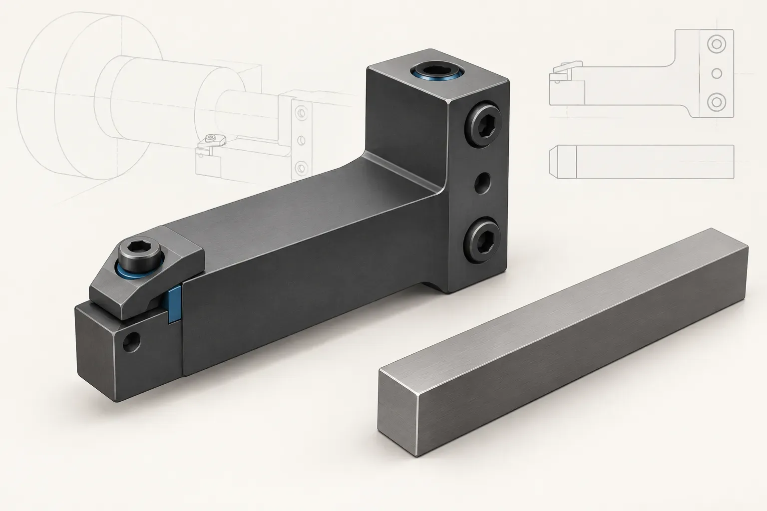
Selecting a BMT external turning tool holder starts with the position required for the cutting tool and the mounting arrangement available on the turret. The holder's overall height is only one part of that review. Step geometry, mounting-hole orientation, working space and the actual tool clamping requirements must remain attached to the exact configuration being discussed.
This guide uses a documented external holder to show which dimensions can be read directly and which purchasing questions still require assembly information. It does not assign an external tool section from a model suffix or claim that one holder fits every machine using the same broad BMT designation.
Identify the external holder before reading dimensions
The BMT40-C20-H55 external tool holder is listed for a BMT turret application. Its record supplies named drawing features rather than a universal installation specification. Read the dimensions with the drawing views that define them.
The A field is a 30 mm lower-step height. The B field is a 55 mm overall side-view height. Neither field is labelled bore centre height in this external-holder record. A comparison that copies the meaning of A from a boring holder would therefore misstate the geometry even if the numbers were transcribed correctly.
Describe the intended external turning tool independently. Include its actual section dimensions, working direction and any identifiable clamping features. The presence of a familiar number in the holder designation is not enough to establish that the complete tool assembly is suitable.
Keep mounting direction and envelope dimensions separate
The following selected dimensions belong specifically to the BMT40-C20-H55 record. They should not be transferred to another size or a visually similar holder.
| Feature | Drawing label | Recorded dimension |
|---|---|---|
| Locating-slot width | C | 12 mm |
| Upper-step length | D | 58 mm |
| Vertical mounting-hole pitch | E | 50 mm |
| Horizontal mounting-hole pitch | F | 60 mm |
| Mounting-face width | G | 75 mm |
| Overall plan-view length | H | 97 mm |
| End-step projection | I | 20 mm |
| Side-opening width | J | 40 mm |
Notice that H describes overall plan-view length, not a mounting-face length. Similarly, J is a side-opening width, not an independently verified tool-section capacity. Keep the feature names visible when creating a comparison sheet; shortening every entry to “width” or “length” removes information needed to judge fit.
Check where the cutting edge must be positioned
The cutting tool's position is determined by the assembled geometry, not by a single holder dimension. Review the tool drawing, the turret reference and the intended working orientation together. If replacing a holder, record the old assembly's position before removing it and identify any adjustment or spacer actually present.
Explain the part feature and the approach required to reach it. An outside diameter, a shoulder or a feature near the chuck can create different space constraints even when the same nominal tool section is being considered. The product listing does not establish a universal allowable projection or collision-free path.
A setup drawing is useful because it distinguishes a required position from an assumed one. Mark the surface from which each height or distance is measured. If the turret documentation and the holder drawing use different views, identify that difference before comparing the numerical values.
Do not substitute appearance for installation instructions
A family photograph can show the general holder form, but it cannot provide tightening values, load limits or a complete list of fasteners. Obtain the applicable clamping and installation instructions for the selected configuration. Do not copy those settings from another holder because its outside shape looks similar.
The same discipline applies to coolant. State the required connection and delivery arrangement, then establish whether the chosen holder supports it. A visible hole or fitting does not prove an internal passage or a particular operating limit.
Inspection before installation should use the drawing and the condition of the actual mating surfaces. This guide does not prescribe an inspection tolerance. Any acceptance limits belong to the relevant manufacturer or machine documentation.
Keep the quotation tied to the external-tool setup
Prepare a request containing the holder designation, turret identification, tool dimensions, intended direction, quantity and a marked-up interface drawing. List any clamping item, spacer or accessory separately and ask that the quotation identify what is included.
Use the tool holders and adapters catalogue for candidate comparison, then retain the configuration record with the enquiry. This keeps a discussion of one external holder from drifting into another size or holder family. A clear purchasing description should preserve both the mounting geometry and the task that the installed tool must perform.
Frequently asked questions
Is overall holder height the cutting-edge centre height?
Not automatically. The example records overall side-view height and lower-step height; the cutting position requires the complete assembled tool and turret references.
Can a side-opening width be treated as tool-section capacity?
No. Use the feature meaning recorded in the drawing and obtain the actual clamping requirements for the intended tool.
What should an external-holder quotation identify?
The exact holder configuration, included clamping items, requested accessories and the tool setup being discussed.