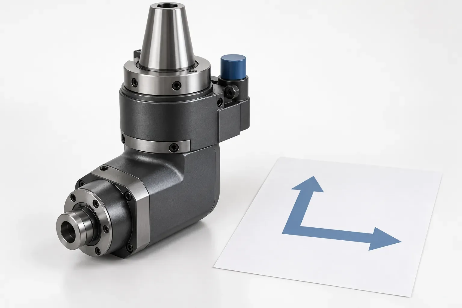
An angle head enquiry should begin with the machine, workpiece and intended cutting direction. The phrase angle head describes a family of attachments, not one universal interface, spindle arrangement or performance level. Before choosing a product, document the operation that would otherwise require a different setup and the geometry that must be reached.
This is a general technical and purchasing guide. It does not claim that a particular angle-head product is available, compatible with a named machine or rated for an unstated speed or torque. Those points require a verified configuration and its documentation.
Define the operation and angle requirement
Provide the part drawing and identify the surface, hole or edge that needs the angled approach. State the intended operation, cutting-tool type and required working direction. Explain whether the aim is to access a feature without repositioning the workpiece or to change the cutter orientation for a specific process step.
A fixed 90° attachment and an adjustable or universal arrangement answer different setup questions. Do not choose between them from a generic product photograph. Describe whether one repeatable direction or more than one approach is required, and keep that choice tied to the feature drawing.
If the job is a replacement, photograph the installed attachment and record its orientation relative to the spindle and workpiece. Include any readable identity. A loose image cannot establish the hidden locating surfaces or machine-side interface.
Verify the machine-side interface and locating method
An angle head must be held and located by a machine-specific arrangement. Request the interface drawing, locating features, stop or anti-rotation details and the applicable fastening instructions. Do not infer the interface from a machine brand, a nominal taper or the shape of a product image.
The stop or locating feature matters because it controls orientation and resists reaction forces within the approved assembly. The relevant document should show where the attachment seats and how its orientation is established. Do not invent a key, block, stud or locating diameter when the drawing does not confirm one.
Keep the machine-side interface separate from the cutter-side interface. A suitable cutter or spindle nose does not prove that the angle head can be installed in the intended machine. Both sides need their own documented checks.
Check spindle direction and working envelope
Record the required cutter axis relative to the machine spindle, the available space around the attachment and the tool path approaching the feature. A right-angle description alone does not establish every envelope dimension or the safe clearance around adjacent tooling.
Review the complete assembly with the selected cutter, holder and any coolant connection. Component length, body width and cutter projection have different datums. Do not turn a product photograph into a clearance or reach calculation.
Operating information should come from the exact attachment and tool setup. This guide does not provide spindle speed, torque, gear ratio, coolant pressure or permissible overhang. Values from another angle head or a different cutter are not applicable merely because the angle appears similar.
Request the documents that make the choice checkable
Ask for the interface and installation drawing, operating instructions, cutter requirements and any orientation or stop details. If the attachment supports a fixed direction, request the direction definition. If it is adjustable, request the adjustment and locking documentation for that exact model.
Keep the machine, workpiece and cutter identities on the same enquiry. A response should identify the proposed attachment, its included items and any conditions needed for the operation. Avoid accepting a general statement that an angle head is suitable without tying it to the feature and machine drawing.
Build an angle-head quotation checklist
| Field | Information to provide |
|---|---|
| Machine | Model, spindle interface and available space |
| Feature | Drawing, operation and approach direction |
| Attachment | Fixed or adjustable requirement and orientation |
| Cutter | Type, holder and projection requirements |
| Installation | Stop, locating and fastening questions |
| Scope | Head, adapters, accessories and quantity |
The tool holders and adapters catalogue provides site navigation, while the OEM / ODM project page can organize a project discussion. Neither page proves that a specific angle head is stocked or compatible. Request a verified configuration before making the purchasing decision.
Send the completed requirement through the contact page. Preserve the returned drawings and conditions with the quotation. A clear angle-head enquiry documents the change in tool direction and the installation evidence needed to assess it, without converting a broad family name into an unsupported machine or performance claim.
Frequently asked questions
Does angle head mean a universal 90° attachment?
No. Angle-head arrangements vary. Identify the required direction, interface and whether the application needs fixed or adjustable orientation.
Can a machine brand identify a compatible angle head?
No. Use the machine interface, locating and installation drawings for the exact setup.
Does a 90° label establish speed or torque?
No. Operating limits belong to the exact attachment and assembly documentation.