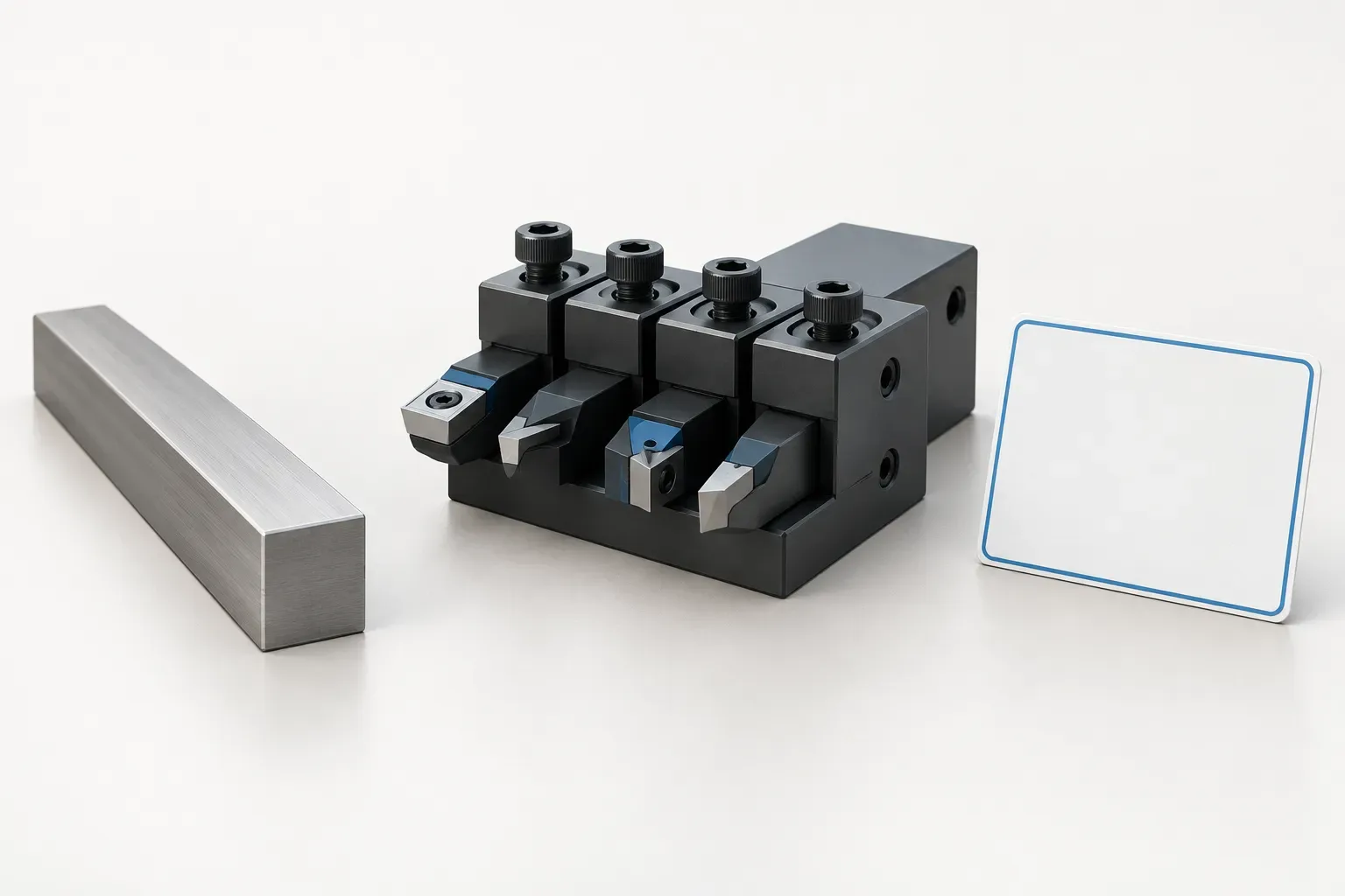
A 16 x 16 mm gang tool holder enquiry identifies a square tool-section requirement, not a complete holder configuration. The mounting arrangement, centre height, clamping details and installed tool position still need to be specified. Treating the section size as the entire purchasing description leaves several independent fit questions unanswered.
This guide focuses on that tool-to-holder interface. Two documented configurations use the same square tool section while recording different centre heights, illustrating why a matching section cannot settle the choice by itself.
State what the square dimensions describe
Use the cutting tool's own drawing or verified identification to establish its section dimensions. Do not substitute the insert size, cutting-edge width or an outside holder dimension for the tool section. The enquiry should identify the actual tool body being clamped and the region intended for gripping.
A nominal section match is an initial comparison, not a complete clamping approval. The holder's applicable instructions must establish how the intended tool is supported and secured. The section label does not supply clamping length, tightening values or an operating load.
If the tool has features that affect the available gripping region, show them on the drawing. A photograph can provide context, but it cannot replace missing dimensions or installation requirements.
Compare centre height independently
The 39 mm centre-height configuration records a 16x16 mm square tool section. A separate 40 mm centre-height configuration records the same section. Their selected fields are shown below.
| Recorded feature | First configuration | Second configuration |
|---|---|---|
| Square tool section | 16x16 mm | 16x16 mm |
| Centre height | 39 mm | 40 mm |
| Base height A | 23 mm | 24 mm |
| Tool-mounting dimension K | 35 mm | 35 mm |
| Overall dimensions | 150x76x40 mm | 150x76x40 mm |
The centre-height requirement must be checked against the machine and assembled-tool references. The records do not establish that a change in tool section can compensate for a height mismatch, or that either holder can be adjusted into every required position.
The overall dimensions are reproduced as a recorded set. Assigning a new axis or physical meaning to each component requires the corresponding drawing. Keep the original feature labels rather than making the table appear more specific than the evidence.
Identify the mounting requirement separately
Show the available mounting surface, locating arrangement and fastening information from the relevant machine documentation. Keep those requirements separate from the square tool-section row. They concern the holder-to-machine side of the assembly.
The cited records list a mounting centre distance of 38–65 mm. That named field is not an established tool-section range or a centre-height adjustment travel. Do not reuse it under a different heading to fill an unanswered selection question.
Where a mounting feature remains uncertain, mark the exact area on a drawing and request clarification. A complete interface review is more reliable than assuming that a tool-section match implies a matching base.
Review the installed tool and neighboring space
Include the cutting tool's required projection and working position in the setup sketch. Identify the part feature that creates the reach requirement and show adjacent tools that restrict the available space. The holder cannot be evaluated only as an empty block.
Do not infer a safe projection, collision allowance or cutting performance from the recorded dimensions. Those conditions depend on the actual assembly and application and require applicable documentation or setup verification.
If an alternative tool or holder is proposed, repeat the comparison using its own record. Include the drawing revision and distinguish a required dimension from an optional preference when recording the proposed change. Keep the original requirements visible so that the alternative is judged against the same section, position and mounting task rather than a simplified description.
Write a complete section-specific enquiry
Provide the actual tool identification, verified square section, required position, machine information, quantity and relevant drawings. Identify the chosen holder configuration and list any separately requested clamping item or accessory.
The tool holders and adapters catalogue can help locate candidates, but the final request should be more precise than a section-size keyword. Ask the quotation to identify what is included and retain the applicable installation instructions with the configuration record. This preserves the distinction between a tool that nominally matches the section and a complete assembly that has been properly selected.
Frequently asked questions
Does 16 x 16 mm identify the complete holder?
No. It describes the listed square tool section. Centre height, mounting and actual clamping requirements are separate selection items.
Do the two cited holders have the same centre height?
No. Their records list centre heights of 39 mm and 40 mm, respectively, despite the shared square tool section.
Does the section size establish clamping torque or safe projection?
No. Those requirements must come from the applicable tool and holder instructions and the actual assembly review.