
CNC CUTTING TOOLS / TECHNICAL CATALOGUEWhatsApp +86 135 1665 2064 ↗
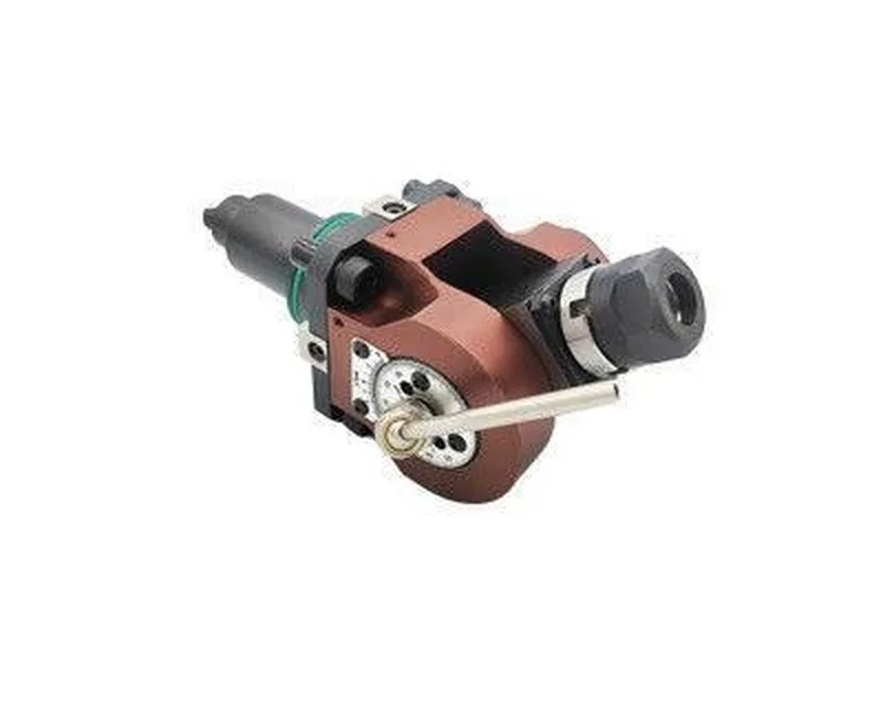
PRECIMILL / TOOLING CATALOGUEBMT Angular Driven Tool Holder: representative catalogue product photographSERIES ILLUSTRATION · CHECK MODEL SPECIFICATIONS
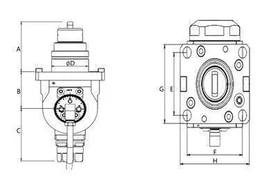
BMT Angular Driven Tool Holder: dimension drawing with catalogue reference labelsCatalogue reference ↗BMT Angular Driven Tool Holder: original model selection and specification table, PDF page 7Catalogue reference ↗

Tool Holders & Adapters

BMT40-ER16 BMT Angular Driven Tool Holder

MODEL / BMT40-ER16

BMT40-ER16: BMT Angular Driven Tool Holder for BMT driven turret. Projection above mounting face (A, mm): 61; Mounting-face to output-centre offset (B, mm): 45. Check the dimension drawing when selecting a replacement.

Projection above mounting face (A, mm)61
Mounting-face to output-centre offset (B, mm)45
Projection below output centre (C, mm)64
Mounting-spigot diameter (D, mm)40
Ask about this model on WhatsApp ↗

Model number is included in your message.
Price, availability and supply scope confirmed by quotation.

Enquire by email ↗
View full specifications ↓

01 / TECHNICAL DATA

Know the specifications.

Catalogue specifications for BMT40-ER16
ParameterSpecification
ModelBMT40-ER16
Product familyBMT Angular Driven Tool Holder
Interface / applicationBMT driven turret
Projection above mounting face (A, mm)61
Mounting-face to output-centre offset (B, mm)45
Projection below output centre (C, mm)64
Mounting-spigot diameter (D, mm)40
Vertical mounting-hole pitch (E, mm)50
Horizontal mounting-hole pitch (F, mm)60
Mounting-face length (G, mm)63
Mounting-face width (H, mm)75
Dimension referenceCatalogue drawing and table, PDF page 7; dimensions in mm unless stated.

02 / PRODUCT OVERVIEW

Check the configuration.

BMT40-ER16 is listed in the BMT Angular Driven Tool Holder range. Angular driven holder with ER tool clamping. Confirm working angle and drive coupling against the supplied machine drawing.

Selection data: Projection above mounting face (A, mm): 61; Mounting-face to output-centre offset (B, mm): 45; Projection below output centre (C, mm): 64; Mounting-spigot diameter (D, mm): 40; Vertical mounting-hole pitch (E, mm): 50; Horizontal mounting-hole pitch (F, mm): 60; Mounting-face length (G, mm): 63; Mounting-face width (H, mm): 75.

Use the attached drawing and original specification table to match the catalogue labels. Dimensions are in millimetres unless otherwise indicated. The main image represents the series; individual sizes may differ. Source: BMT catalogue, PDF page 7.

For an enquiry, send the model, machine and turret details, required tool dimensions and quantity via WhatsApp. Confirm the mounting arrangement and available clearance before ordering.

Content updated:

03 / DIMENSION REFERENCE

Check every connection.

BMT Angular Driven Tool Holder: dimension drawing with catalogue reference labels
BMT Angular Driven Tool Holder: dimension drawing with catalogue reference labels. Click to enlarge. Check the catalogue labels and request any dimensions not supplied.
BMT Angular Driven Tool Holder: original model selection and specification table, PDF page 7
BMT Angular Driven Tool Holder: original model selection and specification table, PDF page 7. Click to enlarge. Check the catalogue labels and request any dimensions not supplied.

04 / BEFORE ORDERING

Clarify the details.

What is included with this item?

Confirm the body, holder, head, inserts and accessories in your quotation. A series illustration does not establish which components are included.

How do I check compatibility?

Compare the listed interface, dimensions and mating components with your application. Send the machine interface, workpiece material and drawing for a configuration discussion.

CONTINUE EXPLORING

More from the collection.

All tooling ↗

TOOLING ENQUIRIES

Send a model. Share a drawing.

Include your quantity, machine interface and application.

Enquire on WhatsApp ↗Enquiry checklist →
WhatsApp ↗